ELECTRICAL
PANEL UPGRADE
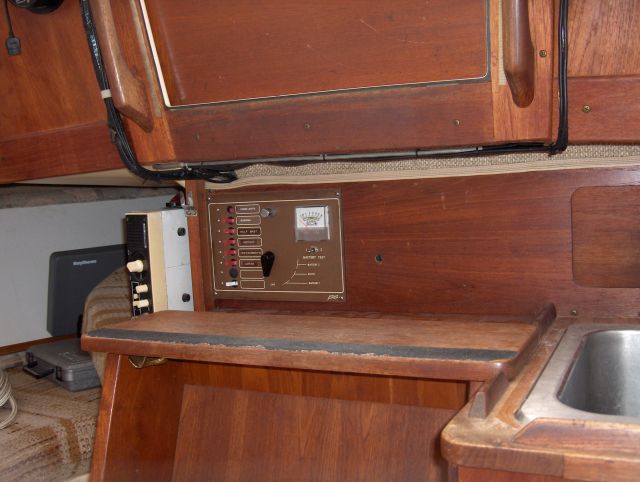
The CAL's
electrical panel was a prefabricated unit just for the CAL. After 20
yrs of use, the voltage
meter's accuracy has rendered it to just an indicator that the needle
moves.
The main battery switch is quite loose making it difficult to determine
which
battery is being used. I was able to add an additional breaker to it
when I
added the refrigeration system and keep it seperate and now I want to
add a
propane control system with leak detection.
I
could just drill through the board that
electrical panel was mounted on, but the engine control panel shares
the same
internal access area behind the steps. If I go too deep on both sides,
the
equipment will not fit. I decided to add additional features and build
it
outward towards the step. I still have a hard time drilling holes
and
decided to try to build the panel in a frame that I could add by
attaching with
just a few screws. That would allow it to utilize the large existing
panel hole
for routing all the wires through without having to cut extra holes for
inserting instruments, switches and additional wiring.
The battery
charge condition
was important to me, I wanted to be able to determine the battery
condition at
a glance. I thought it would be nice to have a couple outlets handy for
,, what
ever,,, and I definately needed to add the propane control system.
After
reading stories of finding dead batteries, I thought it would be nice
to add a
amperage display. If possible to display charging current to the
batteries and
still have it sensitive to display the lower usage currents for
the lights,
instruments, radio, etc....
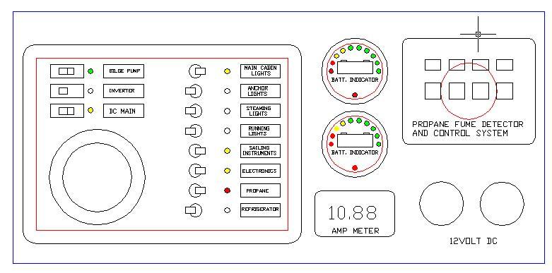
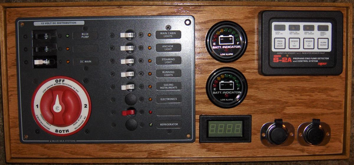
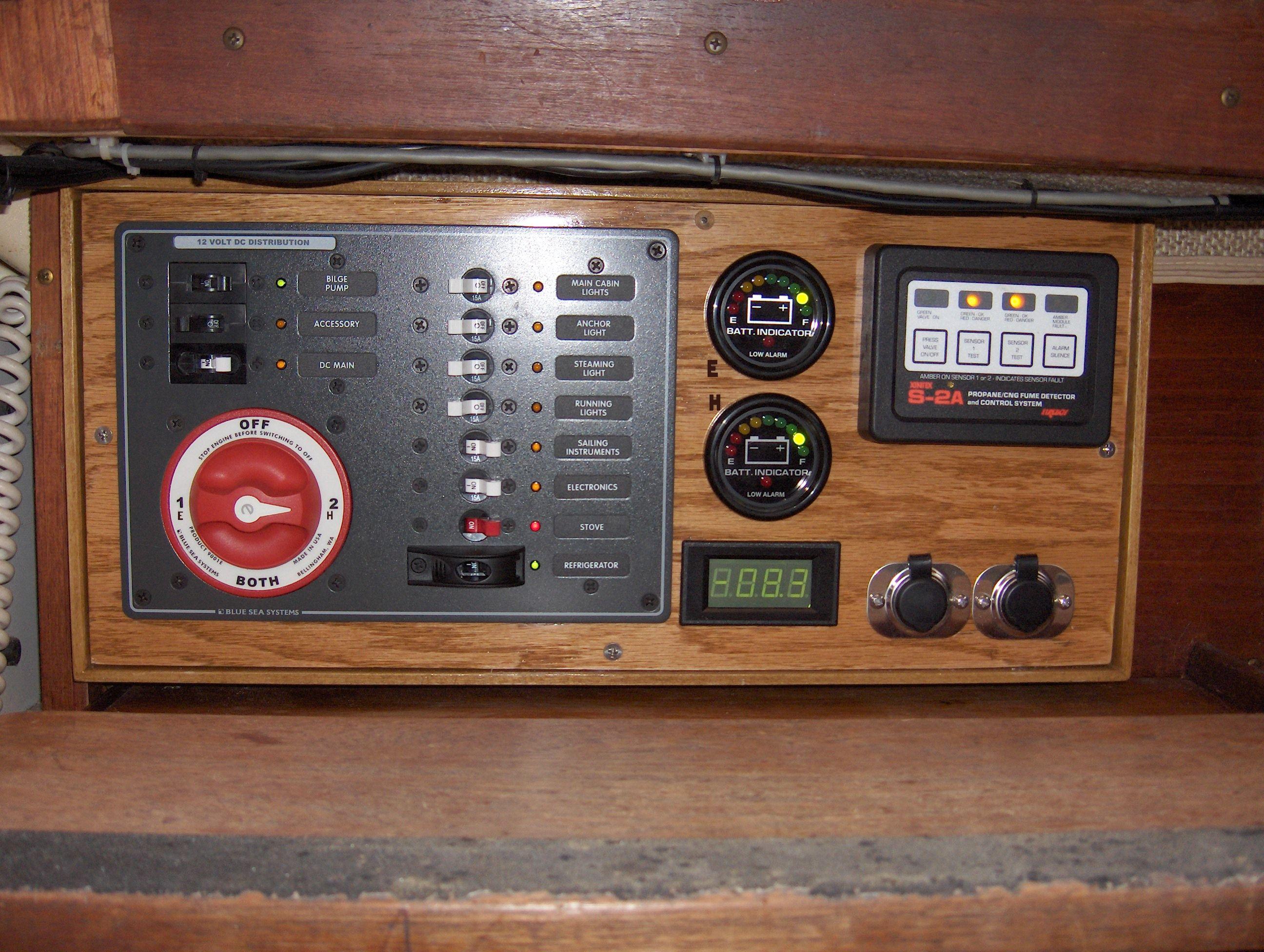
The existing panel position
and wiring installation left little extra working loops of wire,
so I had
to design a new panel that was very similar to the old one. I
searched the
internet and found the Blueseas 8083 panel that was very similar in
size and
function. It had the battery selector switch, 8 breaker circuits and an
additional group of "C" class breakers, one as the master for the
other 8 breakers and 2 additional ones. Class "C" breakers are
not very popular, they are larger than the standard breakers and they
have
wider mounting locations, and rectangular through panel mount instead
of the
more popular round hole mount. I found a couple of the "C"
breakers and populated the panel. I wanted to have the bilge pump on a
separate
circuit and a spare possibly for an inverter.
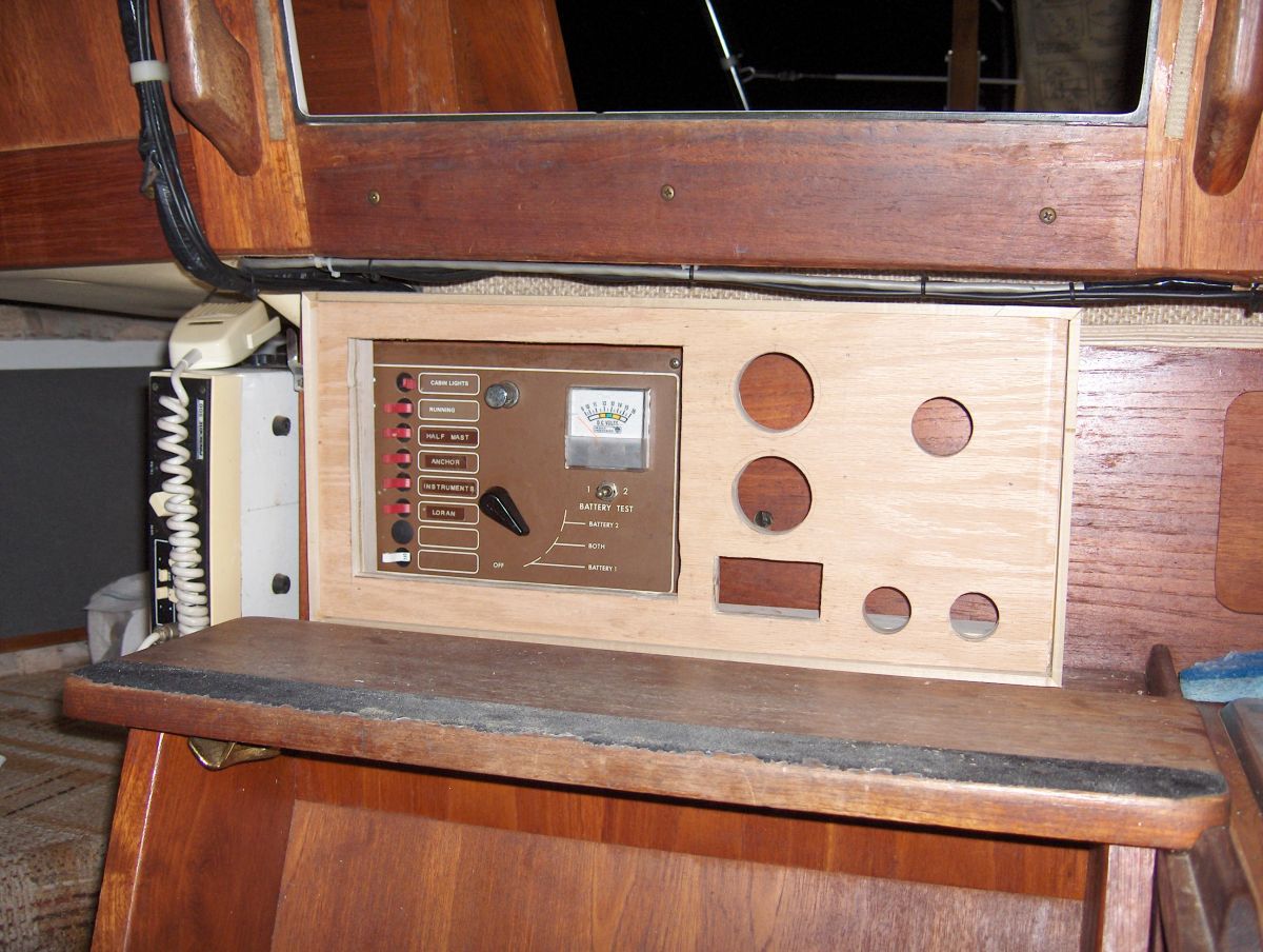 <>The frame and new
installation panel were designed to allow the frame to be attached
to the bulkhead
with 4 wood screws. The panel will be secured to the frame with 4
to 6
screws and can be easily removed. That will allow for me to build all
of the
instruments and electrical panel to the mounting panel and just install
it as
an assembly. The new panel mounts with a 2 1/2" gap just
large
enough for the wiring and instrument backs to clear without hitting the
existing bulkhead.
<>The frame and new
installation panel were designed to allow the frame to be attached
to the bulkhead
with 4 wood screws. The panel will be secured to the frame with 4
to 6
screws and can be easily removed. That will allow for me to build all
of the
instruments and electrical panel to the mounting panel and just install
it as
an assembly. The new panel mounts with a 2 1/2" gap just
large
enough for the wiring and instrument backs to clear without hitting the
existing bulkhead.
This solved the issue of lack of clearance to the engine control panel
that I
installed on the front wall of the cockpit. I recessed the Yanmar panel
to keep
from kicking it.
I decided to change out some of the indicator lights on the panel. I
thought it
would be most wise to have the propane control circuit with a red
indicator and
a red handle circuit breaker.
It the same note of red for dangerous, green should be for good. I
wanted to
have the bilge pump breaker with a green light when ever the bilge pump
was on.
The LED light only draws 15 milliamps which is about the normal
discharge
current of a battery. A 100 Amp-Hr battery would be drained in 9
months, so my
200 Amp-Hr bank would last over 1 1/2 yrs with the LED on. Not a
concern
compared to knowing that you have power to your bilge pump.
Another
circuit I wanted
"green for on" was the refrigerator. It only draws 3 Amps when it
runs and in the fall winter and spring does not run all the time. On
our
November trip the refrigerator loaded with only one bag of
ice, the ice
lasted for 2 days and did not show any evidence of melting. That
allowed the
ice to be used for cooling the beverage of choice. I will change
out this
LED to a green also. The rest of the LED indicators will remain
yellow. The little transparent back lit labels were missing
LPG,
PROPANE, etc., so I had to look for their other label sets. The basis
AC labels
had one that I will end up using.
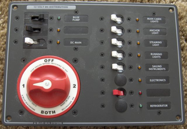
The
8083 panel is very similar is size and
function as the stock panel. The battery selection switch can be
swapped out
with their newer styles is desired. The stock switch is fine with me.
Some
folks may prefer having the starter on a separate circuit from the
instruments. The current battery selection is:
1) = ENGINE BATTERY, AGM 100Amp Hr
2) = HOUSE BATTERY, AGM 200Amp Hr
The
battery switch labels are "glow in the
dark Phosphors”
and UV lights them up. Perhaps there is another project
there in the
future.....
I'm still trying to find other breakers with different colored toggles.
Red for
the propane made sense. I have not found green ones, may have to use a
black
one to show indifference instead of preference.
The battery
condition indicators
were in interesting search. You have the analog needle indicators,
digital
voltage indicators, and LED driven indicators. I looked over the
internet and
decided that I did not want the computerized talking battery condition
charge
discharge monitors; I just wanted condition at a glance. When I worked
at
National they developed a voltage LED driver the LM 3914 that was a
bunch of
cascaded voltage comparators. You could select the low and hi range and
LED
color of choice. I found a pre-packaged unit that would fit a standard
hole
size that indicated charge condition and when the battery is very low a
warning
LED would flash. Red LEDs for low, Yellow for mid and Green for good
voltage.
 I tried it
out on a computer UPS 12 volt battery
power supply. It worked well so I bought another one, one for
each
battery bank.
I tried it
out on a computer UPS 12 volt battery
power supply. It worked well so I bought another one, one for
each
battery bank.
The battery state of charge is indicated by
ten LED's:
5 Green indicates 100
~41%
2 Yellow indicates 40
~21%
2 Red indicates 20% or
less
1 Red indicate flashes
for low alarm
My
goal was achieved, simple display easy to understand and visible from a
distance. It was nice to find the display as a complete unit, I
had
considered using the LM3914 chip and making it, but I prefer to keep it
simple.
The propane controller I decided on has 2 sensors. I
wanted one for near the stove and the other
for a possible cabin heater. I like the Force 10 bulk head mounted ones
with
the small 1" flue. We get together and overnight as much as
possible, even during out low tide period of the year.
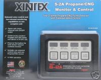
This controller
allows for
manual turning on and off the remote solenoid at the tank with
automatic shut
off if a leak is detected.
It has a warning alarm that will
get you out of bed.
The Unit Retains Its Two Separate Channel Monitoring Capability
And Solenoid Valve ON/OFF Switch.
Plug-In Display Module "Fault" Light/Alarm And Separate Sensor/S
"Fault" Light/Alarm.
(Fault Indicators Let You Know The Module Or Sensor/S Are Not Working
And May Need Repair.)
"Press To Test" For Each Sensor Channel Confirms Function.
S-2A Sensors Are Calibrated To Alarm (Visual And Audible) At 20%
LEL (Lower Explosive Limit).
This Alarm Level Is High Enough To Eliminate Nuisance Alarms But Low
Enough To Allow Time To Take Action.
You
can find the controllers at reasonable cost from various
suppliers, even through EBay.
Putting the plan together:
I tried many cad layouts with different options, disadvantages and
advantages.
I tried
various layouts to try to compress it into the
smallest area. This design would allow for the short
existing wires
to reach the new panel location. It was the best to keep the panel on
the left side.
The additional indicators and controller and outlets can be
easily connected
to the electrical panel and the additional cables can be run through
the large
rectangular hole in the bulkhead from the original panel. This is as
far as I've progressed. The new frame and wood mounting panel are being
stained and
coated with urethane for protection. The plan is to install the panel
assembly
first and run the wiring back to the lazerette for the propane solenoid.
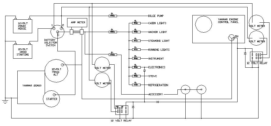
One short term compromise is to use a battery pack to create an isolated 5 volt supply for the digital current meter. It draws 25ma, so a 2.2Amp/hr battery pack will last for 4 days almost 100 hrs of continuous usage. It is on a relay that is energized by the navigation breaker. I can power down all of the equipment connected on the breaker and just use it to turn on the power, voltage and current displays. The plan is to buy a 12 volt to 5 volt isolated power converter.
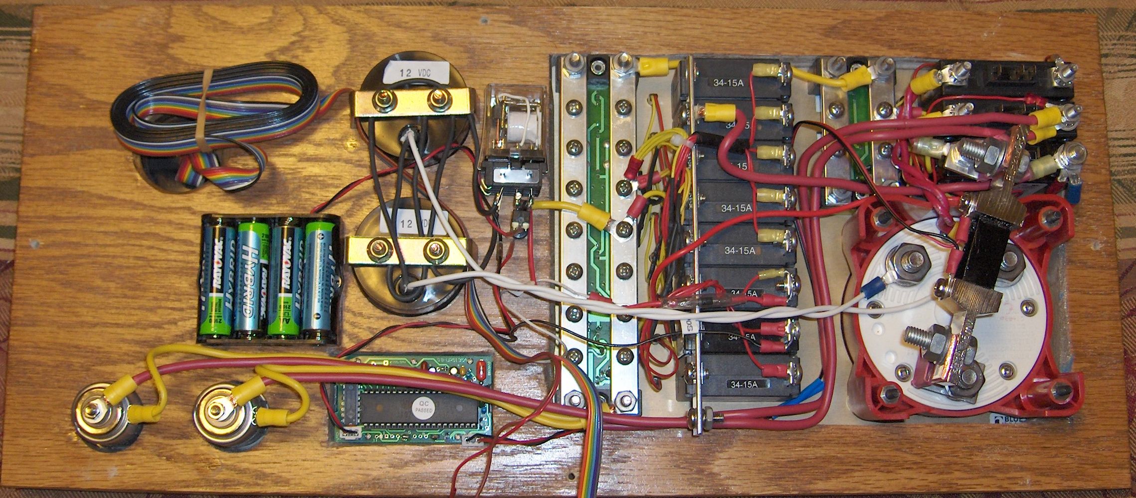
The panel was installed in a few hours and today I modified the Yanmar harness. The alternator 12V output was connected to the large 12Volt battery cable on the starter. I isolated this harness wire and added a 4 gage wire from the alternator to the current shunt. ( 4 AWG is good for 200 Amps and a 100 milivolt drop)When the engine is running, the digital amp display is only displaying the charge current going into the batteries. It is not displaying the additional current from the alternator that is going to the main bus and breakers. Firing up the engine, it displayed around 40 Amps going to the batteries, tapering off to just under 10 amps.
The
epic saga will continue with the stove installation
and the propane locker installation coming soon.
12-12-07 ER.

