Mirror box for the
12.5-inch
If you use Netscape, 'right click' on any image and click 'view image' to
see an enlarged version.
Use the browser 'BACK' button to return.
|
The mirror box is 17" cubed (o.d) ,made of 1/2" American birch
(like Baltic birch, but prettier grain). All plies are
hardwood. There are 3/4" triangles made from poplar glued and screwed
into the corners and running from nearly the top of each corner to the bottom
(remembering to leave space for the mirror cell at the bottom). Poplar
gussets are in each corner for further strength and, importantly, to provide
a support for the baffle and mirror cover to be added (see below). |
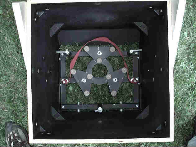
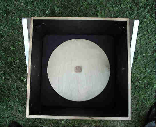
The mirror cell, shown from the top (above) and bottom (below) is almost exactly what the Kriege and Berry book (Chapter 5) describes except that all the metal is bolted instead of welded. This worked great. Another change is that the two crossbars threaded for the 3/8 x 16 collimation bolts are of solid 1" aluminum bar (from Small Parts U-ZSA-16, page 98 of Catalog 21) because I was afraid that the thin steel of the other tubing only had room for a single thread and wouldn't be strong enough to hold the mirror. Another difference is the edge bars (running verically in the picture below) are made from 1 1/4" angle iron. I got the 1/8" steel sheet for the triangles from Small Parts too. The 3/8" all-metal lock nuts that Berry and Kriege say are indispensible (page 144) on the collimation bolts are really hard to find. I had to order 50 from The Nutty Company (click on NUTS; see Grade 8 Torque Lock Nuts), but this online store is very good. The top lock nut was cut in half to minimize its proflile and two layers of EZ Glide pads were used on the corners of the triangles to be certain that the mirror would clear the metal nut.
__________________________________
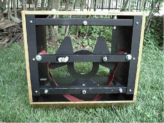 |
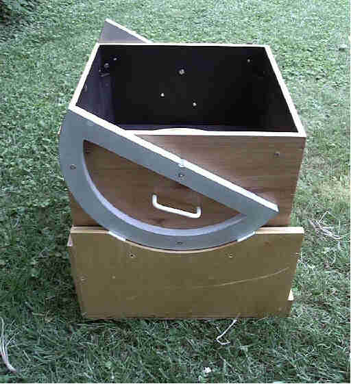
This view is from the bottom of the mirror box. Notice
that the front of the box (on the grass) is beveled as Kriege and Berry recommend
in figure 7.7 of their book. This important
modification allows the mirror box to be lower in the rocker box causing
a lowered center of gravity. My bevel is a straight cut as opposed
to their curved recommendation. The advantage of the straight cut is that
I then was able to reinforce the box with 1/4" ply on the straight edge. A
circle cut from Kydex with drops of Liquid Nails holds the steel triangles
of the cell in place. The nylon belt used for the mirror sling was
from a suitcase strap from
Magellen's.
|
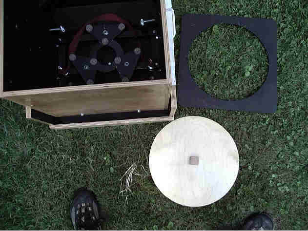 |
A black baffle out of 1/4" Baltic birch (to the right of
the mirror box) velcros onto the gussets in the mirror box (see below).
It has a 13" hole cut in the center and rests 9" below
the top of the box and 3" above the mirror. It blocks light reflecting
from the ground up through the tube. It also provides a platform
for the upper tube assembly to rest on during scope transport. Additionally, the round mirror cover seen here velcros onto the baffle to provide a dust cover for the mirror. |
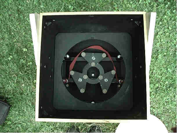 |
The baffle in place.
|
 |
The mirror cover velcroes to the baffle. |
 |
The altitude bearings are of 3/4"-thick medium density
fiber board as recommended by Ray Cash. It is strong and won't warp, but it is brittle, so avoid sharp blows.
The method of cutting circles recommended
by Kriege and Berry (figures 6.6 and 6.7) worked
really well for the altitude bearings, the arcs in the rocker box, the upper
tube assembly rings, and the baffle and dust cover. |
 |
The 3/4" aluminum truss poles attach to the mirror box in a manner similar to that described by Ray Cash. Thus, steel threaded inserts (10-24) are in the mirror box and the bolts go through holes in the aluminum poles (using washers inside and out) to attach them. This approach (as pointed out by Ray Cash) is not very convenient. The poles flop about during assembly (though the more I do it, the easier and less Keystone Kops-like it seems). The problem is that there is very little room in the box (since the UTA has to fit in here during transport). There probably are better solutions, but this approach generates a very rigid telescope that functions well. It is just that your friends will laugh as you set up the scope (but you can laugh back from Australia). |