
|
D/DC model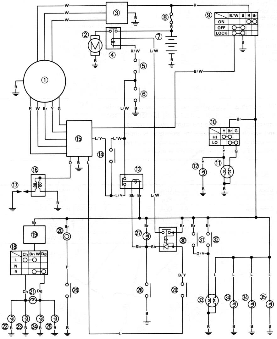 |
W model(redrawn by Tim by tracing wires - the fate of the B/W wire into CDI unit is unknown) |
| B | black | O | orange | B/W | black/white |
| Br | brown | P | pink | B/Y | black/yellow |
| Ch | chocolate | R | red | Br/W | brown/white |
| Dg | dark green | Sb | sky blue | L/W | blue/white |
| G | green | W | white | L/Y | blue/yellow |
| L | blue | Y | yellow | R/W | red/white |
 |
 |
 |
|
| Battery | 12.8V minimum at 20 degrees C
14.0V when charging at 5000rpm |
|
| Ignition coil | primary resistance 0.56-0.84 ohms
secondary resistance 5.68-8.52 kohms |
|
| Spark plug cap resistance | 10 kohms | |
| Minimum spark throw | 6mm | |
| Magneto coil resistance | Between:
brown and green leads 584-876 ohms yellow lead and ground 20-30 ohms |
|
| Alternator stator coil resistance | test pairs of white leads 0.48-0.72 ohms | No data for rectifier |
| CDI pulser coil resistance | red and white leads 656-984 ohms | No data for CDI |
| Starter motor coil resistance | 0.017-0.021 ohms | |
| Starter motor brush length | 3.5mm minimum |
