 Shuttle airlock using bladders
Low air loss and fast transfer times lost.
Shuttle airlock using bladders low air loss and fast transfer times lost.
Bob L. Petersen
The whole idea goes back to the writings on the Atlas rocket in one of the AIAA? books on metals an construction. The atlas rocket uses thin stainless steel it cannot support it's own weight except for the pressure in the tanks. The writings covered load accrossed and off center load. My reseach into using air tanks or fuel or water filled tanks for structural members. Someone has since made a small "model" plane with plastic inflateable wings.
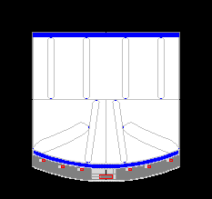
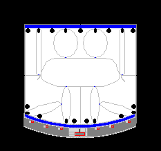
With the front wheel assembly remove from the inside through the door at the top this is the end view of the box that is available to use for the airlock. Working area about 2 feet 4 inches wide, 6 feet 4 inches long and 2 feet 6 inches deep with areas at either end for equipment. I will be using the area at what would be the end by the head incase there is a need for repair or an emergence. The bags themselves started as one simple bag but I realised the middle would sag outward so material going from the front to the back was added. This lead to the circular "tubes" being used, this allows for a low pressure system.
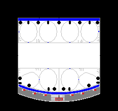
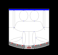
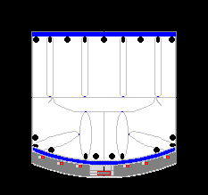
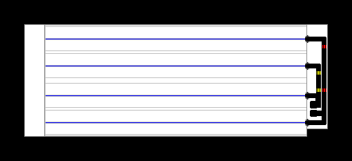
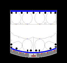 The first picture on the upper left is of the valve inlets that go to the circular tubes with in the bladders. They are oblong or longer then they are wide so that the tubes flatten as much as possible. The second picture on the top is of lines for filling the general area of the bladder. They a circular and all the ones on top are feed by one manifold and the ones on the bottom are feed by another manifold. There are pictures or diagrams of this further down the page. The difference between the 2 drawings in the second row is the first is idealized and second is more as it would be seen with the bladder unevenly hanging out. I will be using the idealized drawings but I know how much the bladders will deform.

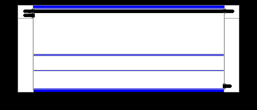
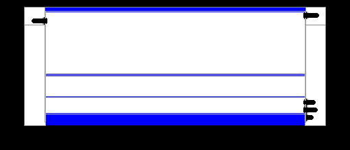
Side View
Overhead View
Underside View
Rule inch = 5 pixels
Parts
Elipese 75 x 215
Circle 160 x 160
Width
width 163
Length
top back difference 30 or 6 inches
bottom back difference 0
top front difference 30 or 6 inches
bottom front difference 10 or 2 inches
total wall to wall 380 or 74 inches
Height
height 148 or 149 or just short of 30 inches
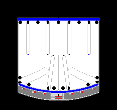
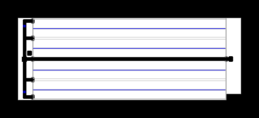
The bladders have cores that can be filled at higher or lower air pressure adjusting the size of the over all bladder circle bladder thin & circle to elipese a the bladder is thicker. Four tubes inside back and for in front. The ones in back connect from back wall to surface. Infalating the two center tubes to circles makes part of the "indention" that makes room for the body. The front has two near the seams for the door opening, they are connected from door side to inner surface. The other two are connected for the center tubes to the side wall. This allows for adjustment of the amount of material around the center of the doors. Moving extra suface material away from the body. ie makes more space for body and easier. Would not want to shot someone out into space throught the airlock.
Bob L. Petersen
Bob L. Petersen

