
The Visual Paradigm for UML (VP-UML) environment provides an intuitive
means to carry out Object-Oriented system analysis and design, where you can
create UML diagrams through simple drag and drop operations. It is a collection
of menus, toolbars and windows that make up the development workspace, which
allows you to create different types of diagrams in a totally visual
environment.
Important features of the Visual Paradigm for UML (VP-UML) environment
include:
![]() Visual hints showing
valid/invalid user actions.
Visual hints showing
valid/invalid user actions.
![]() Sub-diagram support.
Sub-diagram support.
![]() Multi-line captions.
Multi-line captions.
![]() Resource Centric interface for
better usability.
Resource Centric interface for
better usability.
![]() Zone snap in/out special effect.
Zone snap in/out special effect.
![]() Support for UML 1.4.
Support for UML 1.4.
![]() Cut/copy/paste facilities for
diagram elements.
Cut/copy/paste facilities for
diagram elements.
![]() Copy diagram element as OLE to
any OLE containers (such as Word, Excel, PowerPoint).
Copy diagram element as OLE to
any OLE containers (such as Word, Excel, PowerPoint).
![]() Direct editing in diagram
(without property sheets or dialogs) for class, package, operation, and other
element properties.
Direct editing in diagram
(without property sheets or dialogs) for class, package, operation, and other
element properties.
![]() Sophisticated diagram printing
facility.
Sophisticated diagram printing
facility.
![]() HTML and PDF report generation.
HTML and PDF report generation.
![]() Context sensitive help system.
Context sensitive help system.
![]() Multiple look and feel user
interface.
Multiple look and feel user
interface.
![]() Export diagram as JPG, PNG and
SVG image.
Export diagram as JPG, PNG and
SVG image.
![]() Round-trip engineering support.
Round-trip engineering support.
![]() Import model and diagram from
rose file.
Import model and diagram from
rose file.
![]() Import XMI.
Import XMI.
![]() Model generation.
Model generation.
![]() Learning center assisting to
learn UML and Visual Paradigm for UML (VP-UML).
Learning center assisting to
learn UML and Visual Paradigm for UML (VP-UML).
This chapter describes some of the key features
of Visual Paradigm for UML (VP-UML).
When Visual Paradigm for UML (VP-UML) is executed, you are taken to the
Visual Paradigm for UML (VP-UML) Integrated Development Environment where you create and develop your UML
diagrams. Two distinct panes are presented on the screen: the Project Explorer
and the Properties Pane (Figure
1). A Diagram
Pane will appear when an existing diagram is retrieved or a new one is created
via the menu bar or the toolbar. All
these panes can be resized through a click and drag action using a mouse.

Figure 1 The panes in Visual Paradigm for UML (VP-UML)
The project explorer pane contains three views.
They are Diagram Tree View, Model Tree View, and Class Repository View. Each
view shows different perspectives of the project. The following table describes
the three views.
|
Pane |
Description |
|
Diagram Tree View. |
Shows all the diagrams within the
project. |
|
Model Tree View. |
Shows all the model elements within
the project. |
|
Class Repository View. |
Shows all the classes within the
project. |
Table 1 The panes in the Project Explorer Pane

A project may consist of many diagrams. The Diagram
Tree View lists all the diagrams within the project. Through the use of a
folding tree structure, you can browse the names of these diagrams by expanding
or collapsing the folders and perform sorting by diagram type.

Figure 2 The Diagram Tree View
The Model Tree View lists all the model elements
within the current project. Model elements can be dragged to appropriate
diagrams to create a new diagram element. The model element data will then be
shared by these diagram elements. If the model of one of the diagram elements is
changed, the model of the other diagram elements will be changed automatically.

Figure 3 The Model Tree View
A project may contain many classes. The Class Repository View lists all the classes within the current project.

Figure 4 The Class Repository View
There are four pages associated with the
Properties Pane: the Property page, the Preview page, the Documentation page
and the Element Viewer page. The following table describes these pages.
|
Properties Pane |
Description |
|
Property. |
Allows you to edit the properties of the
current diagram or selected diagram elements. |
|
Preview. |
Shows the overall view of the current
diagram. You can quickly access any part of the diagram by drag the rectangle. |
|
Documentation. |
Allows you to enter description for
the current diagram or a selected diagram element. |
|
Element Viewer. |
Displays a detail view of a selected diagram element. |
Table 2 The panes in the Properties Pane
Every diagram and diagram element has its own
properties. The Property pane in the Properties Pane allows you to view and
edit various its properties.

Figure 5 The Property pane
The Preview pane, also known as the Diagram
Monitor, shows an overall view of the diagram. The Diagram Monitor allows you
to navigate the whole diagram pane when the diagram is larger than the display
area of the diagram pane.
Figure 6 The Preview pane
The Documentation pane allows the user to enter
a description about a diagram or a diagram element.
Figure 7 The Documentation pane
The Element Viewer displays detail information of the selected diagram element. For example, you can view the attributes and operations of a Class without the need to open its specification dialog.
Figure 8 The Element Viewer
This diagram pane allows you to edit multiple
diagrams at the same time. The full view of the active diagram is displayed in
the Preview pane of the Properties Pane. You can zoom in to get a close-up view
of the active diagram or zoom out to see wider area at a reduced size.
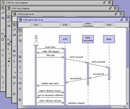
Figure 9 The Diagram Pane
The menu bar at the top allows you to select and perform various operations supported by the tool.
Figure 10 The menu bar
Basic functions such as open a project, save a
project, close a project, print, etc…are provided in the File menu. The following table provides a brief description for
each menu item inside the File menu.
Figure 11 The File menu
Figure 12 The New Diagram submenu
Figure 13 The Reopen submenu
|
Menu Item |
Hot Key |
Function |
|
New Project |
Ctrl-N |
To start a new project. |
|
New Diagram |
|
To start a new diagram or Textual
Analysis, with a cascading menu provided to select one of the eight types of
UML diagrams. |
|
Open Project… |
Ctrl-O |
To open an existing project. |
|
Reopen |
|
To reopen the most recently opened
projects. |
|
Save Project |
Ctrl-S |
To save the current project. If the
project is a new one, this operation is equivalent to “Save Project as…”. |
|
Save Project as… |
|
To save the current project to a
different location. |
|
Close Diagram |
Ctrl-W |
To close the current diagram. |
|
Close All Diagrams |
Ctrl+Shift-W |
To close all the diagrams in the
current project. |
|
Close Project |
|
To close the current project. |
|
Export Active Diagram as Image… |
|
To export the active diagram as image. |
|
Export Diagram as Image… |
|
To export selected diagrams in the
current project as images. |
|
Project Properties… |
|
To view/edit properties about the
project such as general project information, code generation options and report
generation options. |
|
Print Diagram |
|
To print the current diagram. |
|
Print… |
Ctrl-P |
To print selected diagrams in the
current project. A new display will be
presented, allowing you to select the diagrams to be printed, as well as
configuring various printing options. |
|
Exit |
|
To exit Visual Paradigm for UML (VP-UML). |
Table 3 The description of the menu items in the File menu
Functions for editing a diagram such as copy,
paste, select, delete, etc… are provided in the Edit menu. The following
table contains descriptions for each menu item in the Edit menu.
Figure 14 The Edit menu
Figure 15 The Copy submenu
Figure 16 The Alignment submenu
|
Menu Item |
Hot Key |
Function |
|
Undo |
Ctrl-Z |
To undo the last action that you
performed. |
|
Redo |
Ctrl-Y |
To redo the last action that you
performed. |
|
Cut |
Ctrl-X |
To cut the selected diagram elements from
the diagram and copy them to the application clipboard. |
|
Copy -> Copy within Visual Paradigm for UML (VP-UML) |
Ctrl-C |
To copy the selected diagram elements
from the diagram to the application clipboard. The newly created diagram
elements will share the same model element data with the original one. |
|
Copy -> Copy to System Clipboard as
OLE |
Ctrl+Shift-C |
To copy the selected diagram elements
from the diagram to the system clipboard. The diagram elements can then be
pasted to OLE containers like Word, Excel and PowerPoint, which can be edited
directly. |
|
Copy -> Copy to System Clipboard as
Image |
Ctrl+Alt-C |
To copy the selected diagram elements
as an image to the system clipboard. |
|
Paste |
Ctrl-V |
To paste the contents of the
application clipboard to the drawing pane. |
|
Delete |
Delete |
To delete the selected diagram elements
from the diagram. |
|
Select All |
Ctrl-A |
To select all the diagram elements in
the current diagram. |
|
Select All Similar |
|
To select all diagram elements in the
diagram that are the same type as the currently selected diagram element. For
example, if a Use Case is selected, select all similar will select all the
Use Cases in the diagram. |
Alignment |
|
To align the selected diagram elements in one of the following eight ways. Top – the selected diagram elements will be aligned using the top side of the top-most diagram element as the reference of alignment. Bottom - the selected diagram elements will be aligned using the bottom side of the bottom-most diagram element as the reference of alignment. Left - the selected diagram elements will be aligned using the left side of left-most diagram element as the reference of alignment. Right - the selected diagram elements will be aligned using the right side of right-most diagram element as the reference of alignment. Horizontal – the centers of the selected diagram elements will be aligned using the X-coordinate of the first diagram element as the reference of alignment. Vertical – the centers of the selected diagram elements will be aligned using the Y-coordinate of the first diagram element as the reference of alignment. Same Width – the widths of the selected diagram elements will be set to the same value, which is the largest value among the selected diagram element. Same Height – the heights of the
selected diagram element will be set to the same value, which is the largest
value among the selected diagram element. |
|
Find |
Ctrl-F |
To find elements (model elements and
diagram elements) in the current project. |
Table 4 The description of the menu items in the Edit menu
The View menu provides many features for
viewing the diagrams. Zooming in and out function is available for diagrams.
Besides the zooming feature, user can configure the layout by showing/hiding
different panes, resource-centric interface and grid. The following table
describes each menu item of the View menu.
Figure 17 The View menu
|
Menu Item |
Hot Key |
Function |
|
Zoom In |
Ctrl-Plus |
To zoom in the diagram by 10%; the
diagram is magnified by this amount. |
|
Zoom Out |
Ctrl-Minus |
To zoom out the diagram by 10%; the diagram
is diminished by this amount. |
|
Zoom 100% |
Ctrl-0 |
To view the diagram in its actual size. |
|
Resource-Centric |
|
To provide resource icons around
diagram elements for better usability. |
|
Show Extra Resources |
|
To show extra resources of the resource-centric
feature. |
|
Show Grid |
|
To show up the grid at the diagram
pane. |
|
Align to Grid |
|
To align diagram elements to grid. |
|
Toolbar |
F4 |
To display/hide the Toolbar. |
|
Project Explorer |
F5 |
To display/hide the Project Explorer
Pane. |
|
Properties Pane |
F6 |
To display/hide the Properties Pane. |
|
Diagram Pane |
F7 |
To display/hide the Diagram Pane. |
|
Message Pane |
F8 |
To display/hide the Message Pane. |
Table 5 The description of the menu items in the View menu
All the functions under the Code menu are
related to code generation and code reverse engineering. Key features include
configuring code generation options, performing Java language syntax check on
diagrams, as well as reversing code to diagram. The following table contains a
clearer description of each menu item.
Figure 18 The Code menu
Figure 19 The Java submenu
|
Menu Item |
Sub Item |
Function |
|
Java |
Option… |
To set the Java code generation and
Java code reverse engineering properties. |
|
Code Generation Syntax Check |
To check the diagram to see whether it
satisfies the Java language syntax. |
|
|
Generate Code |
To generate the Java code from
diagrams. |
|
|
Reverse Code |
To reverse the Java code to model. |
Table 6 The description of the menu items in the Code menu
Under Option menu, user can configure
various application options including settings related to diagram, project
tree, code generation, etc…. The following table contains descriptions about
each menu item.
Figure 20 The Option menu
|
Menu Item |
Function |
|
Application Option… |
To configure various Visual Paradigm for UML (VP-UML) options,
such as look and feel, and backup level. |
|
Graphics Anti-Aliasing |
To smooth the jagged edges of graphics. |
|
Text Anti-Aliasing |
To smooth the jagged edges of text. |
Table 7 The description of the menu items in
the Option menu
The Tools menu provides access to
various tools, such as HTML/ PDF report generation and project import. The
following table contains descriptions for each menu item in the Tools
menu.
Figure 21 The Tools menu
Figure 22 The Report submenu
|
Menu
Item |
Hot
Key |
Function |
|
Report
-> HTML… |
|
To
generate reports in HTML format. |
|
Report -> PDF… |
|
To generate reports in PDF format. |
|
Import from Rose… |
|
To import Rose project. |
|
Import from XMI… |
|
To import XMI project. |
|
Edit
Stereotype… |
|
To
create, edit or remove stereotypes. |
|
Validate
Model |
|
To
validate the model elements within the current project. |
|
Use
Case Scheduling… |
|
To
perform Use Case Scheduling. |
|
VP-IDE |
Ctrl+Shift-V |
To switch to the VP-IDE environment. |
|
Feedback… |
|
To
submit feedback to Visual Paradigm. |
|
|
|
To
open the |
|
Check
for Update… |
|
To
check for the la |
|
Key
Manager… |
|
To
open the Key Manager to manage the license key files. |
Table 8 The description of the menu items in
the Tools menu
The Window menu is for arranging the
layout of the windows within the application as well as navigating to diagrams.
There are four layouts to choose from: cascade, tile horizontally, tile
vertically, and tile. The following table contains descriptions for each menu
item.
Figure 23 The Window menu
|
Menu Item |
Hot Key |
Function |
|
Cascade |
|
To arrange windows in cascade
formation. |
|
Tile Horizontally |
|
To arrange windows in horizontally
tile formation. |
|
Tile Vertically |
|
To arrange windows in vertically tile
formation. |
|
Tile |
|
To arrange windows in tile formation. |
|
Previous Diagram |
Ctrl-Left |
To switch to the previous diagram. |
|
Next Diagram |
Ctrl-Right |
To switch to the next diagram. |
Table 9 The description of the menu items in
the Window menu
The Help menu contains various resources to help users in using the application. It contains online help, online support, and link to the Visual Paradigm homepage. The following table describes each menu item in the Help menu.
Figure 24 The Help menu

Figure 25 The description of the menu items in the Help menu
|
Menu Item |
Hot Key |
Function |
|
Help Contents… |
F1 |
To show the online help documentation. |
|
About… |
|
To show version/license details about your
copy of Visual Paradigm for UML (VP-UML), as well information about the system and the environment. |
|
Visual Paradigm on the Web ->
Online Support |
|
To get Online Support from Visual
Paradigm Home Page. |
|
Visual Paradigm on the Web ->
Visual Paradigm Home Page |
|
To access the Visual Paradigm Home
Page on the Internet for more information about Visual Paradigm for UML (VP-UML). |
Table 10 The description of the menu items in the Help menu
Below the menu bar, there is a list of buttons
presented as groups of icons, which enables you to carry out various tasks. The
following table shows a detailed description of these buttons and their
functions.
|
Toolbar |
Icon |
Button |
Function |
|
Project |
|
New Project |
To create a new project. |
|
|
Open Project |
To open an existing project. |
|
|
|
Save Project |
To save the current project. |
|
|
|
Save Project as |
To save the current project to a
different project file. |
|
|
|
Print |
To print the diagrams in the current
project. |
|
|
Edit |
|
Copy |
To copy the selected diagram elements
to the application clipboard. |
|
|
Paste |
To paste the copied diagram elements from
the application clipboard to the current diagram. |
|
|
|
Undo |
To undo the last operation. |
|
|
|
Redo |
To redo the last operation. |
|
|
Layout |
|
Alignment |
To select the type of alignment. |
|
|
Align Top |
To align selected diagram elements to
the top. |
|
|
|
Align Bottom |
To align selected diagram elements to
the bottom. |
|
|
|
Align Left |
To align selected diagram elements to
the left. |
|
|
|
Align Right |
To align selected diagram elements to
the right. |
|
|
|
Align Horizontal |
To align selected diagram elements
horizontally. |
|
|
|
Align Vertical |
To align selected diagram elements
vertically. |
|
|
|
Same Width |
To set selected diagram elements to
the same width. |
|
|
|
Same Height |
To set selected diagram elements to
the same height. |
|
|
|
Zoom In |
To zoom in the diagram. |
|
|
|
Zoom Out |
To zoom out the diagram. |
|
|
|
Zoom 100% |
To zoom the diagram to 100% (actual
size). |
|
|
|
Select Zoom |
To zoom the diagram with the selected
zoom ratio. |
|
|
Diagram |
|
Create New Use Case Diagram |
To create a new Use Case diagram. |
|
|
Create Class Diagram |
To create a new Class Diagram. |
|
|
|
Create Class Diagram with Real-Time
Code Synchronization |
To create a new Class Diagram with
real-time code synchronization. |
|
|
|
Create New Sequence Diagram |
To create a new Sequence Diagram. |
|
|
|
Create New Collaboration Diagram |
To create a new Collaboration Diagram. |
|
|
|
Create New State Diagram |
To create a new State Diagram. |
|
|
|
Create New Activity Diagram |
To create a new Activity Diagram. |
|
|
|
Create New Component Diagram |
To create a new Component Diagram. |
|
|
|
Create New Deployment diagram |
To create a new Deployment Diagram. |
|
|
|
Create New Textual Analysis |
To create a new Textual Analysis. |
|
|
|
VP-IDE |
To switch to the VP-IDE environment (available
in Visual Paradigm for UML (VP-UML) Professional Edition only). |
|
View |
|
Show/Hide Project Explorer |
To show/hide the Project Explorer. |
|
|
Show/Hide Properties Pane |
To show/hide the Properties Pane. |
|
|
|
Show/Hide Diagram Pane |
To show/hide the Diagram Pane. |
|
|
|
Show/Hide Message Pane |
To show/hide the Message Pane. |
|
|
Navigation |
|
Previous Diagram |
To switch to the previous diagram. |
|
|
Next Diagram |
To switch to the next diagram. |
|
|
Import |
|
Import from Rose |
To import model and diagrams from a
Rose project. |
|
|
Import from XMI |
To import model and diagrams from an
XMI file. |
|
|
Export |
|
Export Diagram as Image |
To export selected diagrams as images. |
|
Report |
|
Generate HTML Report |
To generate reports in HTML format. |
|
|
Generate PDF Report |
To generate reports in PDF format. |
|
|
Help |
|
Help |
To view the online help documentation. |
Table 11 The description of the buttons on the toolbar
The message pane (Figure 26) is responsible for displaying messages to the user. For example, when the user performs Java language syntax check, the checking result will be displayed in the message pane (Figure 27).

Figure 26 The message pane

Figure 27 The messages displaying in the message pane
Besides, after the user performed searching of elements using the find function, the find results will be displayed in the message pane (Figure 28).

Figure 28 The find results displaying in the message pane
The following table contains a list of special
features in Visual Paradigm for UML (VP-UML). It briefly describes what special functions can be carried
out in Visual Paradigm for UML (VP-UML). Some of the features may have mentioned before.
|
Special Features |
Description |
|
|
The |
|
“What-You-See-Is-What-You-Get” visual interface |
An interactive ‘What-You-See-Is-What-You-Get’ visual interface, allowing you to carry out editing actions more effectively. |
|
Resource Centric |
A user interface based on the Resource Centric approach is adopted to enable UML diagrams to be constructed intuitively with minimal efforts. With the novel interface, only valid editing resources are grouped around a graphical entity, totally eliminating invalid operations during diagram construction. |
|
Realistic containment interaction |
A realistic interaction when an entity is dragged in and out of a UML container region. |
|
Visual hints indicating invalid editing operations |
A popup warning sign appears when an invalid editing operation is attempted to minimize errors in the diagram. |
|
Automatic containment rule detection |
A facility to automatically detect the containment rule for a container, e.g. an Actor will not be contained in the System Boundary, even if they are moved into the container’s region. |
|
Sub-diagrams support |
A facility to associate a diagram with other lower level UML diagrams to facilitate levels of abstraction and increase the traceability among UML diagrams. |
|
Textual Analysis |
A facility for performing textual analysis based on the Use Case description or problem statement. With this facility, the designer can identify domain objects, build a data dictionary, and perform system analysis with ease. The analysis can be performed using a single problem statement in the conventional way, or alternatively you can use a Use Case description and treat it as a problem statement to perform a textual analysis to identify the domain objects. |
|
Copy diagram elements to system clipboard as OLE objects |
Support the copying of diagram elements to the system clipboard as OLE objects which can be directly edited in any OLE containers, such as Microsoft Word, Excel and PowerPoint. |
|
Copy diagram elements to system clipboard as images |
Support the copying of diagram elements to the system clipboard as image. |
|
Layout diagram elements |
The layout facility in class diagrams and collaboration diagrams allows you to re-layout the diagram elements neatly. |
|
Java code generation |
Generates Java code from the class
diagram. |
|
Java code reverse engineering |
Generates model from Java code. |
|
Java language syntax checking |
Validates the class models against Java language syntax. |
|
Model validation |
Validates the model elements against UML syntax. |
|
Printing |
Visual Paradigm for UML (VP-UML) provides a sophisticated
printing facility that produces professionally-looking printouts. There are
many functions you can use in the print preview pane, such as adjusting the
margins, fits in page or multiple pages, zooming, editing the header/footer. |
|
XMI importer |
Allows you to import an XMI project. |
|
Rose importer |
Allows you to import a Rose project |
|
Report generation |
Allows you to generate HTML or PDF
report. It converts all the diagrams in a project into HTML or PDF files,
together with a navigation menu. |
|
Visual Paradigm Products Update |
The Visual Paradigm Products Update allows you to update Visual Paradigm for UML (VP-UML) very easily in just a few steps. |
Table 12 The special features in Visual Paradigm for UML (VP-UML)
Other online demonstration:
