Some Of The Knowledge Needed To Do What I had Planned. Page 2
Turbojet Turbofan Afterburners Ramjet And Scramjet

|
These three joined diagrams or pictures are of a turbojet turbofan ramjet. The Scramjet is not shown. The pictures are from the NASA Glenn Research Engine Simulator. I am using them so that the reader will be familiar with them. The turbojet and the turbofan do not have there burners or burner cans pictured. This is where the combustion takes place. Part of the air goes into the cans and is combined with the fuel, then ignited. This allows the temperature to get as high as possible while the burner can is cooled by the air entering it. This high temperature inside the cans helps to keep the engines lit. The bypass air is then mixed with the air from the burner cans. This then will pass through the turbine I both the turbojet and the Turbofan.
The major difference is the fan this is an air bypass system. This bypass air is pushed by the power generated by the what is otherwise a turbojet engine. The fact that this bypass air is not compressed saves on energy losses. The work that is transferred to the fan allows for higher temperatures and thus for higher efficiency. On a military airplane the fan bypass would be enclosed and will also be boosted by the afterburners. This makes the turbofan capable of high power output per weight for short bursts, such as in combat. yet still very efficient at loitering or cursing speed.
One of the versions of the scramjet is like the ramjet except the Scramjet cone in the middle is smaller. This lowers the compression and does not slow the air down as much which means the air is not as hot. This is necessary because that much compression would make the air to hot to add any heat from combustion before the maximum temperature the metals could take would be reached.
Some simple tools for insight.
These are very good though.
The NASA Glenn Research Engine Simulator
The Engine Simulator Program
The engine simulator program that was put made at the Glenn Research Center. The Glenn Research Center is funded by NASA and it was NASA that paid for the program. This simulator is aimed at College Level and above because of some added features. The simulator has limits that are adjustable. These limits are set at what would be normal maximum for simulating current designs. The simulator can be modified so that the maximum altitude can be adjusted up. The simulator can not change the laws of physics and there are points beyond which the simulator would not be accurate at all. The simulator involves the use of a lot of files so I have put it at another location so that it will not use up all the bandwidth here. There is backup to everything at that location.
This is not setup to simulate a scramjet but it can be adjusted to make it fly into the hypersonic region of flight or greater then mach 5. A ramjet normally has a compression of 8 to 1. a scramjet on the other hand has almost none or about 1.2 to 1. After you have adjusted both the inlet and the outlet to active cooling and taken it to 50,000 feet. Then take it as fast as it will go without over heating. The simulator will not allow for the adjustment of the compression but the expansion of the nozzle can be adjusted. If the compression could be adjusted down then heat from compression would of course go down. By switch to turbojet and then adjusting the compression down then going back to ramjet the simulator will show what the inlet will look like but it will not figure the heat from compression correctly.
The NASA Glenn Research Wing Simulator
The Simulator For Wings
This simulator for wings the it can tell the lift and drag of a wing event with different angles of attack. This is from the Glenn Research Center also and is funded by NASA. The more complex designs and those with large sweeping curves are good for slow to mediums speeds (100 m.p.h. to 500 m.p.h.) This is no what this design is aimed at. In fact the whole term cruising speed does not apply to this design. The wing design will have more in common with the X-3, X-15, SR-71, XB-70. and the F-5. The X-3 used a solid shaped piece of metal for it's wing. Since they are not as much based on the shape of a airfoil they are fall under the name compression lifts. The XB-70 and the F-5 were high lift to area designs that was based of the earlier planes. The X-15 used a thicker and not solid wing with the first of the lifting bodies. As far as the X-planes go this will be where they lose their wings and just go with the lifting body. The SR-71 is a winged lifting body. The long body is supported by the lifting body which is at different angle of attack from the wings. The name for this design class of wing is the fin wing. As it will spend most of its time just as a fin.
The simulator is goes up on to 250 Miles Per Hour that is enough to do take off and landings. Beyond that on takeoff the wings are just fins. The setting for use of plate or flat wing is the one of interest. This will provide the zero lift at zero angle of attack. The 3 to 4 G acceleration will do the lifting.
The circle or round wing setting is for figuring the effect of the cross wind on the fuselage. Which is very important during takeoff and landing. At takeoff as the speed increases the weight on the wheels will be less as the speed increases. Finally switching from holding the plane down to using the control surfaces to help lift it off should be done at the correct speed.
The answer to how to achieve liftoff is in the front landing gear of the old F-7u. The raising of the nose by so many degree. Not as much as the F-7u. It had a problem with it breaking at that length. That was also with a arresting hook which caused the front wheel to snap down.
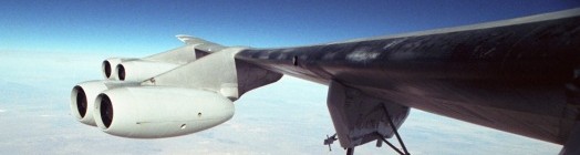
The Bend In A Long Wing Under Normal Load.
|
This picture is good example of one that seems almost scary. The wing is bent so much under normal load. The Presidents Plane and some of SAC's plane are 747Es. These are high powered 747s. I saw them do a land stop and takeoff one trip down the runway. When the plane was climbing after takeoff you could see the bend in the wings.
How many times can they bend like that. How long will they last if they do not bend that much ever. They new how many times they could do that before they would need to change the tires. The tires smoked stopping and they takeoff while they are still hot. This is stress strain and creep in action.
The structure of the wing is much like a bridge. There are beams running out from the fuselage or body of the airplane. They all bear the weight of the plane in flight. If the wing is a standard airfoil then more of the weight is borne at the front of the wing, as apposed to the trailing edge. The trailing edge is usually thinner and but will be required to carry it's part of the load. This can be done by making the load try to twist the back of the wing up to transfer the load to the thicker part of the wing.
The design I chose was to be as simple as possible. The use of airfoil surfaces would not useful. The angle of attack will determine the lift. Though most of the flight out the plane is accelerating at better then 3 G. plus the 1 G loss to gravity. The lift of the plane is meaningless. The beams will be required to bear a thrust of engines along with the weight of the plane. The fact that the engines will be putting out thrust equal to 2 times the weight of the ship is a large load. The Chose of a near flat wing design means that this load can and will be borne by the skin of the wing. The normal wing structure just serving to keep this from buckling under the load. The equations for calculating the force on the beams come from the book The Machinery's handbook.1 They list load carrying ability in 2 dimensions according to the shape. The equation for this application is the one for a uniform load along the length of the beam.
The load on the area of the engines in covered by a circular shape trying to maintain it's shape. The outer wing area is again a simple beam. This part of the wing is really only needed for it's control surface which at that distance from the body have the ability to imparting torque causing a twisting motion on the fuselage as well as adjustments to what would normally be considered the lift. The other dimensions is handled by throttling the engines.
Bob L. Petersen
Bob L. Petersen
I did not buy this book I was most likely one of the books left in apartments by student who dropped out of the tech school. The some of others that came by that way was a books on welding and refrigeration.
Bob Petersen

