Time Constants
Objective: the objective of this lab was to investigate the properties of RC circuits and the frequency dependence caused by capacitors and inductors.
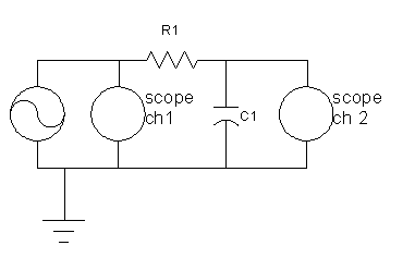
Part 1: RC Phase Shift
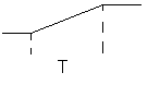
For an integrating circuit like the one above, and for part 2, a square wave input comes out like the following, with Vout = V°T/(RC).
After assembling the the circuit from above we had to measure the time displacement from the period in CH1 to the period in CH2 and express it in radians for various frequencies and then plot the results and then find the break frequency find the break frequency. the break frequency, fb is equal to 1/RC was calculated to be 30.3 KHz at the break frequency the phase shift is equal to 45° or π/2.
| Frequency (KHz) | Time Displacement (sec) | Time displacement (radians) |
| 1.0 | 0.05 | |
| 2.0 | 0.04 | |
| 4.0 | 0.03 | |
| 5.0 | 0.025 | |
| 6.0 | 0.02 | |
| 8.0 | 0.02 | |
| 10.0 | 0.016 |
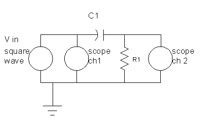
Part 2 RC Integrator:
For part 2 we used the same circuit in part 1 but the function generator was set with an output of fb/10 or 3.03 KHz. The square wave observed shows a time displacement from -Vin to Vin + 2Vin (1-e^-1) , of τ = 40µs, compared to that of τ = RC = 33µs we can see a percent error from the expected of 17.5%. Now when we set the input frequency to fb*10 (303KHz) the slope of the output is approximately 588,200 this slope should be equal to the constant of integration, of the percent error for the constant of integration is %
Part 3 RC Differentiator:
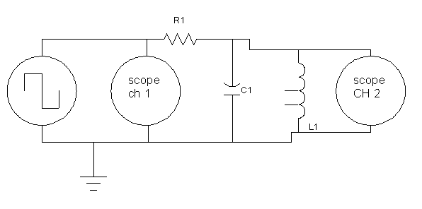
Part 4 Ringing: