

For a verbal description click here.
"I've heard of rusty gates, open gates and sagging gates but never leaky gates". This is not that kind of gate. It's the gate in a field effect transistor. "I've seen lots of transistors because the place I work sells them. Never seen a gate on a one of them." It's inside and too small to see. "Does it swing?" Only if you play the right kind of music through it.A gate leak detector is called that because a capacitor charges up on peaks of the radio signal and then the charge leaks off through a resistor. This circuit is based on the original grid leak detector which was made with vacuum tubes and is almost as old as radio itself.
The gate of the JFET acts like a diode because that is basically what it is. When the incoming signal goes positive the gate junction conducts charging the capacitor. When the signal swings back negative some of the charge on the capacitor leaks off through the resistor but because the time constant is long compared to the length of an RF cycle the amount of leak off is a small percentage of the charge. The capacitor remains charged up to the peak of the RF cycle minus the forward drop of the gate-channel junction which is often approximated as 0.65 volts. The RC time constant is short compared to the audio frequencies that are the modulation. Therefore the charge on the capacitor tracks the instantaneous value of the modulation. At least that's the way it's supposed to work. It does work. I can tune in 2 out of 3 local stations and although the audio output is rather small it is enough to hear clearly, volume turned up all the way, on a pair of amplified computer speakers.
But when I connect my oscilloscope to the gate of the FET I cannot see any evidence that rectification is taking place. The reason is that the unmodulated carrier level is 200 mV peak. Even at 100% modulation the incoming signal is not enough to forward bias the gate channel junction. When I look at the plate I see some asymmetry of the audio signal which tells me that detection is occurring due to nonlinearity in the FET's transfer function around the zero bias point. Which means that detection is occurring in the drain circuit not the gate circuit.
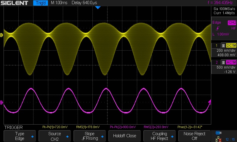
Now let's see what I can see with a signal generator instead of off the air modulation. I needed the received signal data to decide on the output setting for the signal generator.
For a verbal description click here.
My next step was to connect a Schottky diode from gate to ground as shown below. The volume level increased by about 26 dB. The scope showed that detection was taking place. Some might argue that this is nothing but a crystal set with an F E T audio amplifier. If someone did I would be hard put to refute it.

For a verbal description click here.
I've taken 3 days off from rebuilding a power supply for an HW101 which I am trying to get on the air. Maybe after I finish that job I'll tackle a regenerative detector using an F E T.
This page last updated Thursday, August 02, 2018.