Chapter 2 Theory of Operation.
2.1 Design Considerations.
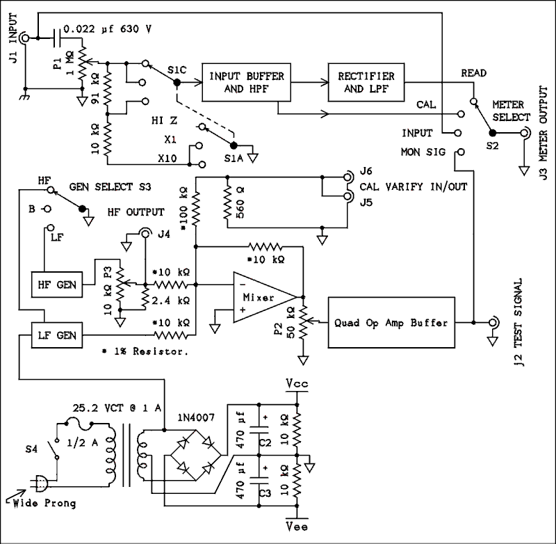
2.2 Overall Diagram.
2.3 Circuit Description.
2.3.1 Control Panel. 2.4 Operating Characteristics.
2.3.2 Low Frequency Generator.
2.3.3 High Frequency Generator.
2.3.4 Linear Mixer and Output Buffer.
2.3.5 Input Buffer and High Pass Filter.
2.3.6 Linear Rectifier and Low Pass Filter.
2.3.7 Power Supply.
2.3.8 Calibration.
Chapter 2 Theory of Operation.
There is no doubt that you can build and operate this instrument without any understanding of how it works. However an understanding of the circuit will enhance both the building and operating experience. In the construction phase you be aware of why a particular component goes in a particular place and how the parts work together to make up the whole instrument. In the operating phase you will be less likely to make mistakes if you understand why you are setting a particular control in a particular position. Before reading this chapter you might want to study section 1.2 in chapter 1.Back to Fun With Tubes.
Back to Fun With Transistors.
Back to Table of Contents.
Back to Top.2.1 Design Considerations.
The number one design consideration was to build a project that others could easily duplicate in their own shop. It would have been easy for me to use parts on hand which might be one of a kind items. I even thought of building it into an old Heathkit 5248 IM distortion analyzer case which would have the panel marked correctly, a correctly scaled meter, and the meter range switch complete with resistors. I don't see them on eBay very often so I don't think many were sold. I decided against all that and have provided a source for every part used.The next decision was to include a meter or have the builder use an external meter. The standard AC metering circuit used ever since the HP 400A uses a rather special switch. Any manufacturer who builds such a meter has to special order the switch from the switch manufacturer. I could have designed a circuit using a switch like the ones used in this project but The actual switching would have been done with reed relays and some logic between the switch and the relays. That could get expensive and bulky so I rejected it. So I asked myself, "Is this likely to be the only distortion analyzer the builder has?" The answer I came up with was "No". I think that someone who has come to the point of wanting to measure IM distortion probably already has a harmonic distortion analyzer. Or at the very least an AC voltmeter such as one of the HP 400 series or a Heathkit 5238. To be perfectly frank about it, if you don't have either of these you are not ready to measure IM distortion.
A problem which made itself known was noise modulation on the high frequency generator. The current version is number 4. The first one didn't make it past the breadboard stage. The second was built but before the project went live on the web I found there was a great deal of amplitude drift as the transistors warmed up. The third one was a Wien bridge oscillator that was FET stabilized. It had a relatively small amount of noise but the noise spectrum seemed to be 1/f which made the meter pointer take occasional large jumps. I found that some of the noise was from the op amp but the FET was a large contributor. Changing the op amp from an LF353 to a TL072 and the FET from an MPF102 to a 2N5951 went a long way toward fixing the problem. Some changes in resistor values which made the FET a smaller player in setting the gain has reduced the noise so the residual reading with the test signal connected directly to the test input now is 0.02% with an almost steady pointer.
When I was with Western Kentucky University I built a Heathkit IM5248 Im analyzer for the university. Heath claimed in the calibration procedure that the residual could be gotten down to 0.006% but I couldn't get it close to that. To be honest about it I can't remember for sure what it was but I think it was somewhere in the neighborhood of 0.015 to 0.02%. The two analyzers I bought on eBay are worse than that and I was unable to get them lower. I think I am doing as well as is possible with simple analog circuits.
One final consideration was the use of either a 2 wire or 3 wire line cord. A 3 wire line cord gives maximum safety but it also creates ground loops which might tempt the user to employ a 3 to 2 adapter or even cut off the ground prong thus losing any polarizing protection. A polarized 2 wire line cord gives a lot of safety and the transformer provides sufficient isolation to make the instrument safe to use on a workbench. The instrument you use as the meter will provide the safety ground without creating a ground loop.
Back to Fun With Tubes.
Back to Fun With Transistors.
Back to Table of Contents.
Back to Top.2.2 Overall Diagram.
This particular instrument was made to be used with an external AC voltmeter such as the voltmeter function in the HP 333/334A harmonic distortion analyzer. It could also be used with any of the HP 400 series of AC voltmeters. (Note: The early ones are vacuum tube based while later ones are silicon based.) Another alternative is the Heathkit 5238. The one distinguishing feature of all of these meters is the lowest range is 1 millivolt full scale. I'm sure there are many other meters in existence but I can't quote make and model. It could also be used with a DMM but I don't recommend this.
The analyzer consists of two parts, a test signal generator and a measuring circuit.
The test signal generator consists of three parts, the low frequency generator (LF GEN), the high frequency generator (HF GEN), and the linear mixer (op amp) that combines the two. In models designed for use in North America the LF GEN delivers a 60 Hz sine wave signal. This signal is derived from or synchronized to the 60 Hz line frequency. If the LF GEN is allowed to run freely its frequency will be off from the line by a small amount, one or two Hz. If the device under test has some 60 Hz line frequency in its output the LF GEN will alternately add to and subtract from this signal and cause the meter to waver. I don't know if European instruments use a 50 Hz test signal or allow the 10 Hz difference to appear in the metering circuit. In the design shown below the LF test signal can be interrupted by grounding a point in the circuit.
The high frequency generator (HF GEN) delivers a 7,000 Hz sine wave signal. Its output amplitude is adjustable for users who may want to employ a ratio other than 4 to 1. A point in the oscillator circuit is grounded to turn off the signal source when desired.
The two signals are combined in an op amp linear mixer and buffered to the test signal output. The linear mixer does not produce any significant intermodulation of the test signal.
It is usual to adjust the LF signal to be four times the magnitude of the HF signal. Other ratios are sometimes used but this is the most prevalent.
The combined 60 Hz and 7,000 Hz signal is fed to the input of the amplifier under test. The output of the amplifier is properly terminated and the voltage across the load is fed to the input of the analyzer. There is an attenuator at the input to permit adjustment of the level. After the attenuator a high impedance buffer prevents loading of the attenuator while providing a small amount (2) of gain.
The input buffer is followed by a high pass filter. This filter removes the 60 Hz signal. What is left is the 7,000 Hz signal which likely has been amplitude modulated by the 60 Hz signal due to nonlinearity in the amplifier under test. Think of the 7,000 Hz signal as a carrier that contains some percentage of amplitude modulation. The modulating frequency is the 60 Hz signal. The average amplitude of the 7,000 Hz carrier is used to give the metering circuit a signal that defines 100% modulation.
Next the signal is fed to a linear rectifier or detector in modulation terms. The next step is a low pass filter that removes any measurable evidence of the 7,000 Hz carrier signal. This leaves only the 60 Hz modulation that was present on the 7,000 Hz carrier. The meter selector switch is then placed in the read position and the percentage modulation is read. This is the percentage of IM distortion in the amplifier under test.
Back to Fun With Tubes.
Back to Fun With Transistors.
Back to Table of Contents.
Back to Top.2.3 Circuit Description.
The internal schematic of each of the 5 blocks (modules) will be given below and each one will be accompanied by a functional description of the operation.2.3.1 Control Panel.
The control panel contains 3 rotary switches, 3 potentiometers, and 6 coaxial jacks.In the upper right corner of the overall diagram above you will find S2 the meter selector switch. This switch is being mentioned first because it is referred to in several paragraphs. The rotor of the switch connects directly to the meter output jack J3. The position of this switch determines what is being read on the external meter.
In the upper left corner of the overall diagram above you will see a pot, a two ganged switch, and a few other components. The jack J1 feeds signal to the input position of S2 the meter selector switch. This enables the input voltage to be easily measured at any time. The input also feeds through a 0.022 μf capacitor to the top of P1, a 1 Meg ohm linear potentiometer. The purpose of this capacitor is to prevent any DC that might be present at the input jack from being passed to the input of the first amplifier. The wiper of the pot feeds through switch S1C to the input of the input buffer and HPF. The switch is shown in the "HI Z" (high impedance) position. When the switch is in this position the minimum input resistance is 900 k ohms when P1 is at maximum and can be as much as 1 Meg ohm when the pot is set lower. When the switch is set to the "X1" (times 1) position the wiper is still connected through S1C to the input. The bottom of the resistor network is connected through S1A to ground. This places a 100 k ohm resistor from the wiper to ground which gives the pot a pseudo logarithmic taper. This will make the input level easier to adjust when the input voltage is greater than 3 volts. In the "X10" position S1C connects the input to the junction of the two resistors which throws in another X10 attenuation. This makes it possible to test amplifiers with powers up to 200 watts. You may be wondering why I used the letters A and C instead of A and B. The letters are molded into the plastic of the switch.
Switch S3 selects either the LF GEN or HF GEN or BOTH. When the connection to the module is grounded the signal from that particular module is turned off.
Pot P3 is for adjusting the level of the HF GEN relative to the LF GEN. The resistor that is connected between the wiper and ground is to give the control a pseudo logarithmic taper and place the most used setting at approximately mid rotation.
P2 connected between the op amp output and the input of the output buffer adjusts the amplitude of the test signal. A resistor located inside the output buffer module provides the pseudo logarithmic taper for the control. The main power on/off switch, S4, is ganged with P2.
The output of the output buffer goes to J2 as well as the MON SIG position of S3. This permits convenient measurement of the test signal which is required to set the 4 to 1 ratio of the two frequencies.
The remaining two positions of S2 are to allow calibrating the instrument to 100% and reading the percentage of distortion.
J4, J5, and J6 are used in calibrating the instrument for accurate readings. Their functions will be explained later.
Back to Fun With Tubes.
Back to Fun With Transistors.
Back to Table of Contents.
Back to Top.2.3.2 Low Frequency Generator.
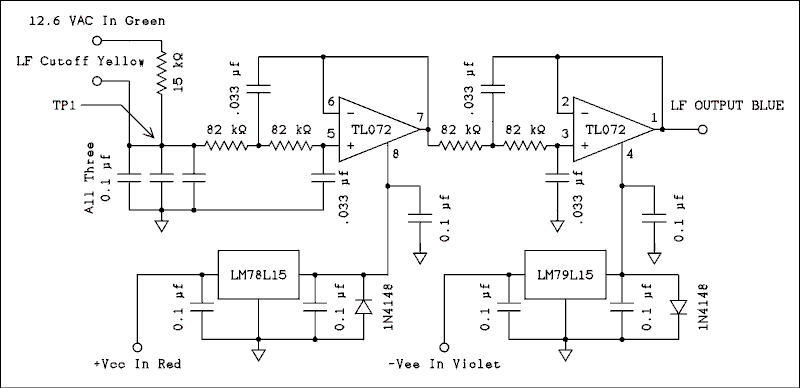
The 60 Hz low frequency is derived directly from the power line via the 25.2 volt center-tapped power transformer. The signal on such a power transformer secondary is somewhat distorted due to the rectifier diodes and filter capacitor that are connected to it. The signal is initially filtered by a 15 k ohm resistor and a 0.3 microfarad capacitor made up of 3 0.1 uf capacitors in parallel. The junction of the resistor and capacitor is brought out so it may be grounded through switch S3 to shut off the 60 Hz signal.
The signal from the junction of the 15 k ohm resistor and the 0.3 uf capacitor is additionally filtered by a pair of 2 pole active low pass filters for a total of 5 poles of filtering. The filtered 60 Hz signal has less than 1 % harmonic distortion. The 60 Hz sine wave signal is brought out of the shielded enclosure to be fed to the linear mixer to be described later.
Local power supply regulation is provided to ensure complete signal isolation between modules.
Back to Fun With Tubes.
Back to Fun With Transistors.
Back to Table of Contents.
Back to Top.2.3.3 High Frequency Generator.
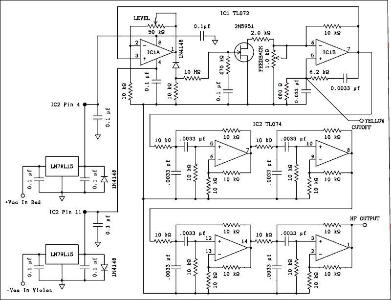
The 7000 Hz signal is generated by a Wien bridge oscillator that is regulated by an FET. The oscillator section uses IC1B as its gain element. The series section of the frequency determining feedback loop has 20 times the impedance of the parallel section. This reduces the voltage at pins 6 and 7 which reduces distortion by applying a smaller voltage swing to the FET. If the FET were in cutoff the loop gain would not be high enough to start and sustain oscillation.
In the instant after power on the voltage at the gate of the FET is zero and the drain to source resistance is very low. This places the 2 k ohm resistor in parallel with a portion of the 1 k ohm pot in the negative feedback loop. This sets the oscillator loop gain higher than is needed for linear oscillation. The oscillator starts and IC1A amplifies the signal and applies it to the rectifier. This applies a negative voltage to the gate of the FET which increases its drain to source resistance thus lowering the loop gain of the oscillator. The oscillator settles in at an amplitude that does not produce clipping in IC1B. The 1 k ohm feedback pot sets the loop gain so the FET operates at or near the center of its control range.
The antihunt network consisting of the 470k resistor and the 0.1 uf cap prevents overshoot and hunting of the oscillator amplitude. The 10 k ohm resistor from the diode anode to ground ensures equal resistance for charging and discharging the capacitor. Unequal resistances will cause bouncing of the oscillator amplitude. The 50 k ohm pot in the feedback loop of IC1A permits adjustment of its gain for setting the oscillator amplitude to the desired value.
The output of the oscillator then passes through a band pass filter consisting of 4 op amps and associated resistors and capacitors. A band pass filter was used rather than a low pass filter because the oscillator output contains harmonics plus some low frequency noise. I found to my sorrow that the filter will not remove noise modulation on the 7 kHz signal.
Local power supply regulation is provided as with the previous module and all those to follow.
Back to Fun With Tubes.
Back to Fun With Transistors.
Back to Table of Contents.
Back to Top.2.3.4 Linear Mixer and Output Buffer..
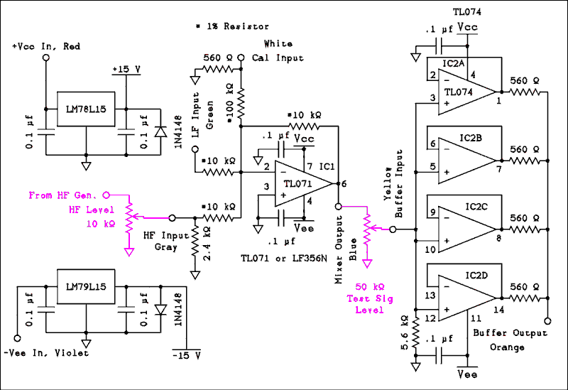
Any radio people reading this may be confused. The word "mixer" has very different meanings to radio and audio engineers. This kind of mixer is nothing more than an adder. The two signals are added together linearly and the goal is NOT to form sums and differences but simply end up with the same two frequencies in the output that went into the two inputs.
The parts shown in Magenta (purple) are not inside the mixer module but will help in understanding the circuit. The mixer is comprised of the single op amp, three 10 k ohm resistors and a 100 k ohm resistor. The low frequency signal is fed into the mixer at full level. The high frequency signal is fed through a 10 k pot that allows the relative level of the two frequencies to be adjusted by the operator. A 2.4 k ohm resistor from the pot wiper to ground places the 4 to 1 ratio at the approximate center of rotation. There is a third input through a 100 k ohm resistor and we will come back to this later. The low and high frequency signals emerge from the mixer on pin 6 of the op amp.
The combined signal is fed through a 50 k ohm linear pot to the output buffer. A 5.6 k ohm resistor from the wiper to ground gives the pot a pseudo logarithmic taper. The four amplifiers in the IC are operated effectively in parallel. These op amps have a tendency to oscillate if terminated in less than 470 ohms. The 560 ohm resistors prevent this and make sure there won't be any high circulating currents caused by small differences among the amplifiers. The combined output resistance of 560 / 4 = 140 ohms should be low enough to drive any amplifier you can think of. One possible exception might be a grounded grid or common base configuration.
Back to Fun With Tubes.
Back to Fun With Transistors.
Back to Table of Contents.
Back to Top.2.3.5 Input Buffer and High Pass Filter.

The input buffer is a single op amp connected as a noninverting amplifier with a gain of two. Although the input attenuator provides a return to ground for the noninverting input a 10 megohm resistor is included on the circuit board to permit the module to be tested independently of the rest of the analyzer.
The low pass filter employs a quad op amp. Each filter section consists of two 0.022 uf capacitors and two 10 k ohm resistors. The cutoff frequency is at the geometric mean of 60 Hz and 7000 Hz. The reason for this is filter attenuation curves are geometric rather than arithmetic. Each filter section also has a gain of two to bring the signal up to a level which will ensure it is well above the noise floor.
The signal is taken out directly from the output of the last op amp for connection to the input of the rectifier. A portion of the output voltage is tapped off via a screwdriver adjustable potentiometer for standardizing of the instrument during operation. This is the signal that is fed to the "CAL" position of S2.
Back to Fun With Tubes.
Back to Fun With Transistors.
Back to Table of Contents.
Back to Top.2.3.6 Linear Rectifier and Low Pass Filter.

The linear rectifier is a standard absolute value circuit. Its performance can be improved by using 1% resistors. The diodes are inside the feedback loop so there is no need for matched diodes.
The output of the rectifier feeds a four section low pass filter. Dual op amps have been used to minimize capacitive coupling between sections. Once again the cutoff frequency of the filter was originally set at the geometric mean of the two frequencies but had to be modified.
The unattenuated output of the last op amp has been brought out in case it is ever needed for testing and troubleshooting. The calibrated output is fed through a screwdriver adjustable potentiometer to the "READ" position of S2.
Back to Fun With Tubes.
Back to Fun With Transistors.
Back to Table of Contents.
Back to Top.2.3.7 Power Supply.
A two wire line cord with a polarized plug connects to the power line. The wide prong of the plug connects to one side of the power transformer. Signal is taken off of one side of the secondary and sent to the LF GEN as explained earlier. A bridge rectifier connects across the entire secondary. The output of the bridge is filtered by two electrolytic capacitors. The center tap of the transformer and the common point of the two capacitors is grounded to provide symmetrical positive and negative voltages of approximately 19 and -19 volts. The two 10 k ohm resistors serve to discharge the capacitors after power is turned off. The output of the power supply is taken to each module where on board three terminal regulators reduce and regulate the voltage for each module independently.Back to Fun With Tubes.
Back to Fun With Transistors.
Back to Table of Contents.
Back to Top.2.3.8 Calibration.
A detailed calibration procedure is given at the end of the assembly chapter. And is duplicated in the General Maintenance section. To actually perform the calibration you are referred to these sections.The "CAL VERIFY IN/OUT" jacks provide a means of injecting a signal from a function generator while monitoring its frequency and output voltage. This signal is injected to the summing point through a 100 k ohm 1% resistor. The 560 ohm resistor is large enough for any signal generator to be able to drive it while lowering the input impedance to a low enough level to prevent the open inputs from picking up extraneous noise.
The HF output is used to measure the voltage and frequency of the high frequency generator and the external function generator is set to match the voltage and at a frequency that is 60 Hz higher than the HF Gen. The signal is fed to the summing point through a 10 k ohm 1% resistor. When the two signals at the "Cal Verify Input" and the HF input are equal in amplitude the output of the mixer consists of one 7 kHz signal and another that is 60 Hz higher in frequency and 1/10 the amplitude.
This is a single sideband with carrier signal that is modulated at 10%. If a true double sideband with carrier signal that is 10% modulated is examined on a spectrum or wave analyzer it will be found that each sideband has a voltage amplitude of 5% of the carrier amplitude. A single sideband with carrier signal must have a sideband amplitude that is twice that for a double sideband signal to produce the same effective modulation percentage. This permits the calibration adjustment to be set for a 10% reading.
Back to Fun With Tubes.
Back to Fun With Transistors.
Back to Table of Contents.
Back to Top.2.4 Operating Characteristics.
These are not the operating instructions for this instrument. They will be given in a later chapter. This is just an overview.The low frequency generator is derived from the secondary of the power transformer. As such it will change as line voltage changes. I think short term changes in line voltage are not large enough to introduce significant errors in the measurement. None of us are hooked on to our grandfather's power utility. Provision is made for adjusting the ratio of low frequency voltage to high frequency voltage. The test signal selector switch is set to LF only and the meter selector switch is set to MON SIG (monitor signal). The test sig level pot is set for some convenient level such as 1 volt. The test signal selector is set to HF only and the HF level pot adjusted for 0.25 volts. To test an amplifier the test signal selector is set to BOTH.
The test signal is connected to the input of the amplifier under test. The amplifier's output is terminated with a resistive load of the proper value. The output power is adjusted to a desired level short of clipping. The output of the amplifier is fed to the input of the measuring circuit. The meter selector is set to CAL and the input attenuator is adjusted for a reading of 100%. Then the meter selector is changed to READ and the meter's range switch is changed downward until the amount of distortion can be accurately read.