Winding Coils - Page 4
Oscillator Coil
This coil is needed in all of the superheterodyne radios.. It has two separate windings.Here are the steps for winding the oscillator coil.
- Cut 2 inches of the mailing tube. A hacksaw is recommended
but any fine toothed saw will do the job. Don't waste your time and
effort on scissors or knives. You'll likely break the scissors and it's
almost a certainty that you will cut yourself with a knife. The material
is too tough for these tools and even if you do succeed in using them
the cut end of the mailing tube will look extremely ragged and you will
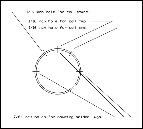
be ashamed to show it to friends.- Use a pencil or pen to mark off the cut piece of mailing tube as follows.
Mark 1, 3/8 inch from one end.
Mark 2, 3/8 inch from mark 1.
- Use a 1/16 inch drill bit to make a hole in the mailing tube at mark 2.
- Now mark three points for drilling holes spaced about 1/4 of
the circumference of the tube apart. These holes should be on mark 1.
Drill these holes with a 7/64 bit. Offset the center hole by about
30 degrees from the 1/16 inch hole as shown in the figure below.
- Now wrap the coil form (mailing tube) with Double Stick Scotch
Tape. Be as careful as you can not to leave any wrinkles or bulges
in the tape. If you don't do a perfect job it's not the end of the world.
Don't cover up the 7/64 inch holes if you can help it.- Use the drill or a small nail to punch through the
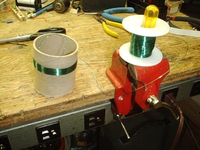
tape at the 1/16 inch hole.- Now you are ready to start the first winding. Use the Green wire
which is 26 gauge.- Remove the plastic from the spool of green wire and place it over
something that will allow it to turn while holding it in place. I used
a small screwdriver clamped in a small vise.- Push one end of the wire through the hole at mark 2 from the outside.
Pull 3 or 4 inches of wire through on the inside of the tube.- Hold the wire on the inside of the tube and begin the first turn.
The sticky tape will hold the wire in place and after about half a turn
you won't need to hold the wire inside the tube any more. Tuck the
end of the wire inside to keep it out of your way.- Wind the turns so each turn is touching the previous one. This will
not cause a short circuit because the wire is coated with insulating enamel.- Wind 3 turns. The picture below shows how to setup for winding the coil.
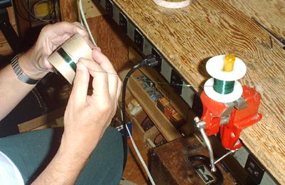
DON'T WIND THE COIL BY HOLDING THE FORM STILL
AND MOVING YOUR HAND AROUND AND AROUND THE
COIL FORM. When you do this every turn puts a twist in the wire.
After a while the wire will start to kink and then get into a hopeless
tangle. Roll the cylinder (mailing tube) around in your hand like
the take up spool on a real to real tape recorder. (Rotate the coil
form [mailing tube] around its axis.)- The Double Stick tape makes it possible to set the coil down in
mid winding and come back to it later. It won't unwind while you
take out the garbage or answer the telephone. But if your 2-year
old grandchild gets a hold of it all promises are cancelled.
- After you have wound 3 turns use the 1/16 inch drill to make a hole at the
location indicated for the coil tap and just so the drill bit does not touch the
last turn of the coil.- Wind two more turns for a total of 5 so far. The fifth turn should cross over
the middle of the hole.- Push about 3 inches of the wire through the hole for the tap you just made.
- Now pull some more green wire off the spool and push the end through
the same hole where the end of the first green coil goes to the inside
of the coil form. (Mailing tube.)- Hold the end inside the tube and start winding in the direction
as if this coil were a continuation of the first coil. THIS
IS VERY IMPORTANT! The new coil MUST go as if it is a continuation of the first coil. In fact it is.- Wind 38 turns.
- Make a 1/16 inch hole at the location shown in the figure for the end
of the coil and almost touching the last turn.- Wind 2 more turns, cut the wire and push the end through the hole.
- Now get 3 4-40 x 1/4 machine screws, 3 4-40 nuts and 6
number 4 solder lugs. The screws and nuts are available at any
hardware store worthy of the name. For the solder lugs you
may have to go to an electronics supply store either brick and
mortar or on line.- Mount a solder lug on the inside and outside of the tube at
all 3 7/64 inch holes.- On the outside point the lugs at right angles to the axis
of the tube and on the inside point the lugs inwards away
from the nearest end.- Tighten all screws.
- You now have 4 wires coming through the tube to
the inside and 3 solder lugs on the inside to solder them to.
- To prepare the end of a wire to be soldered to a lug do the following.
- Pull the end of the wire to the lug where you want it to go.
- Leave quite a bit of slack in case you break the wire before you solder it.
- Cut off the excess and bring the end of the wire out of the end
of the tube so you can get at it.- Tare off a small piece of sand paper about 1 inch by 1/2 inch.
Fold it in the middle of the long dimension with the sand on the inside.- Place the end of the wire inside the sand paper, pinch it
between thumb and for-finger and pull it along the wire to
its end. You will see the green enamel come off and the copper
wire underneath will be revealed. Work around the wire until there
is a bright copper area at the end of the wire.- On the two wires that come through the same hole remove the enamel
as far into the tube as you can reach.- Twist these two wires together to become effectively one wire.
- Pass the end of this double wire through a hole in the center solder lug
of the three, pull it tight, wrap it around and solder it in place.- Solder the remaining two wires to the solder lugs that are closest to
where they come through to the inside of the tube.- The picture shows the solder lugs.
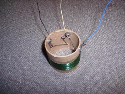
- Now solder lengths of colored insulated hookup wire to
the lugs on the coil form as follows.
- Yellow wire to the lug where the two wires come together.
This is the tap on the coil.- Green wire to the end of the coil
as indicated in the drawing above.- Black wire to the beginning of the coil
as indicated in the drawing above.This completes the oscillator coil. Now, that didn't hurt a bit did it!
The colors for the wires were not selected on a personal whim. Traditionally in tube equipment certain wire colors have been associated with certain functions. B+ or plate supply wires are red, wires from plate coils to the plate of a tube are blue, wires from grid coils to the grid are green, and wires to the opposite end of grid coils are yellow. These last may supply grid bias or AGC/AVC (Automatic Gain Control/Automatic Volume Control).
Use your back button to return to where you were before.
This page last updated June 11, 2002