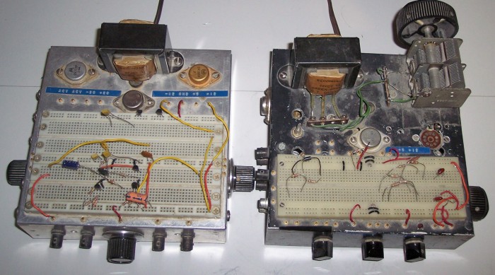
"Breadboarding" refers to a method of wiring circuits in a manner that is easily visible, quick and easy to construct, easily changed, and can be taken apart leaving the components in a state of reusability.Breadboarding of semiconductor circuitry is best done on a plastic socket that can accommodate integrated circuits as well as discrete transistors. These solderless breadboards are available from Circuit Specialists and Global Specialties just to name two. I have three breadboarding sets I constructed a very long time ago, back in the 70s I think. One of them is pictured on the "What do I need to have fun with transistors" page and the other two are shown below.
The one on the right was built on a recycled chassis in a hurry. The tube socket was not used for tubes but for a small crystal oven that I have a few of. The variable capacitor was originally intended for use with an NE561 phase locked loop AM radio which I was interested in at the time. Unfortunately this IC is no longer available but I will try to design something with currently available devices and post it for your enjoyment.
The paragraph below applies to both breadboards. The TO-3 package in the center is a fixed 5 volt regulator. There are two TO-3 transistors, only one is visible on the right hand chassis, one on each side of the chassis. One is PNP and the other is NPN. These are pass transistors for the positive and negative adjustable power supplies. The plus and minus supplies track and are controlled by a single pot. This was well before the development of the adjustable three terminal regulator. The PC board for the internal power supply is mounted under the chassis. There are BNC and phono connectors for getting signal to and from the circuit without the use of clumsy clip leads on the board. Two of the BNCs are terminated with 50 ohm resistors and the other two are open. There are two pots on the left board and 3 on the right one. I recommend 1 k and 10 k. The power transformer is a 24 volt center-tapped at 1 amp.
The only thing you will find it difficult to duplicate are the little gold pins for connecting a single wire. As far as I can tell these are no longer available. The only solution I can think of is to bring wires from the pots, BNCs, etc, up through small holes in the chassis and insert them into the breadboard socket where needed. These wires will break in time and the under side of the chassis should be easily accessible so they can be replaced when needed.
The original power supply circuit is relatively complex and there is no use for you to try to duplicate it. If I were building it today here is the circuit I would use.
For a verbal description click here.
All of these three terminal regulators have a tendency to oscillate. The two 0.1 uf capacitors on the LM309K should be soldered from each pin to a grounding lug mounted on one of the screws holding the TO-3 package to the chassis. The case does not have to be insulated from the chassis. The 317 and 337 must be insulated from the chassis and silicon grease must be used on the mica insulator to conduct heat away from the regulator. The 0.1 uf and 10 uf capacitors associated with these devices must be mounted as physically close to the regulators as possible and with very short leads.
The two diodes on the output are to prevent the positive regulator from being drawn negative or the negative regulator from being drawn positive. This can happen in an op amp circuit if there is a wiring error or a defective component. If this should happen the best is that a regulator can latch up with its output voltage near zero and the worst is that a regulator can be burned out.
Don't think you have to exactly duplicate what I did. Everybody has different ideas and needs so each one built will be different. They are not expensive to build so when your needs change you can build another one just as I did.
Have fun with transistors but be careful not to fall into a hole.
This page last updated August 2, 2006.