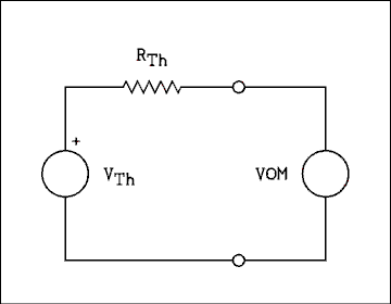
Figure 2.1 Voltmeter measuring output voltage of Thevenin circuit.
For a verbal description click here.
Chapter 2 Test Equipment.
2.1 The Volt-Ohm-Milliammeter (VOM).
2.2 The Electronic Voltmeter.
2.3 The Digital Multimeter (DMM).
2.4 Choosing The Correct Test Meter.
2.5 Analog Versus Digital Meters.
2.6 The Oscilloscope.
2.6.1 The Digital Storage Oscilloscope (DSO)
2.7 The Signal Tracer.
2.8 Miscellaneous Test Equipment.
2.9 Instruction Manuals.
Chapter 2
Test Equipment.
Troubleshooting is impossible unless you have test equipment and know how to use it. In actual fact, someone who is very skilled can do more with a simple voltmeter than someone who has little skill and a workbench full of test equipment.It is every bit as important to choose the right test instrument as it is to operate it correctly. If you try to use a VOM (volt-ohm-milliammeter) to measure voltages in high impedance circuits or an electronic multimeter to test a logic circuit, you will get nowhere fast. This chapter will discuss several of the most common pieces of test equipment and explain what they can and cannot do.
Back to Fun with Transistors.
Back to Fun with Tubes.
Back to Table of Contents.
Back to top.
2.1 The Volt-Ohm-Milliammeter (VOM).
The volt-ohm-milliammeter (VOM) has been around longer than any other test instrument. In spite of this it remains very popular. The reasons for its popularity are: reliability, portability, ruggedness and low cost.By definition a VOM has no amplifying devices in it. It contains only resistors, a few diodes, perhaps one capacitor, some batteries and, of course, the meter movement.
As the name implies the VOM can measure voltage, current and resistance. Most VOMs will measure both AC and DC voltage while the current ranges are DC only. The internal batteries are used in measuring resistance. A VOM will not measure the reactance of an inductor or a capacitor.
Ranges and scales.
There is a great amount of confusion about the correct usage of the terms range and scale. They are NOT interchangeable and should never be used as such. The range expresses the limits or extent over which the meter can measure with a given setting of the controls. The scale refers to the graduations which the pointer moves across.It is NOT correct to say "the meter is set to the 10 volt scale". It is correct to say "the meter is set to the 10 volt range".
It is correct to say "the scale reading is 5.3". Notice that there are no units given. The units and the power of ten by which the scale reading must be multiplied come from the setting of the range switch.
Reading the meter.
Even a very high-quality VOM will not give useful results if the operator does not interpret the reading correctly.A typical VOM may have 8 voltage ranges, 6 current ranges and 5 resistance ranges. There are never separate scales for each range. It is necessary to multiply the scale reading by the correct power of ten to obtain the correct reading.
Example 2.1.
A VOM is set to the 2.5 volt range. There is no 0 to 2.5 scale but there is a 0 to 250 scale. The reading on this scale is 195. What is the voltage being indicated?Solution:
The range switch is set to the 2.5 volt range (given), which means that the meter can measure voltages anywhere in the range of 0 to 2.5 volts. It is therefore impossible for the reading to be 195 volts. If the meter were indicating full scale (all the way to the right), it would be indicating 2.5 volts. Also, the pointer would be over the 250 mark on the scale. It is necessary to divide the scale reading by 100 to obtain the correct voltage reading. 195/100 = 1.95 volts, which is the correct reading.Example 2.2.
A VOM is set to the 500 milliampere range and the scale indication is 27 on a 0 to 50 scale. What is the meter indicating?Solution:
The 0 to 50 scale corresponds to the 0 to 500 milliampere range; therefore, the scale indication must be multiplied by 10 to obtain the correct reading. 27 times 10 = 270 milliamperes.Notice that you do not multiply the range switch setting by the scale reading. You choose the scale which is related to the range switch setting by a power of 10 and multiply the scale reading by that power of 10 to obtain the reading.
Most experienced VOM users simply look at the scale, mentally put the decimal point in the right place and take the reading. As so often happens, the marvelous computer called the human mind makes all of these calculations without even thinking about them.
AC voltage.
All VOMs have AC voltage ranges. Because the meter movement will respond to DC only, two or more diodes are used to change the AC to DC. Because of the nonlinear voltage - current characteristic of a diode, the meter indication is not directly proportional to voltage. This nonlinearity is compensated for by the meter manufacturer printing nonlinear scales on the meter face. These special scales are almost always in red and clearly marked AC. These special scales only apply to the lowest one or two AC ranges of the meter. Be extra careful to always read the correct scale.Input resistance.
A VOM does not have a fixed input resistance. It depends on the setting of the range switch. All VOMs have a sensitivity rating which is stated in ohms/volt (ohms per volt). To obtain the input resistance of a VOM, it is necessary to multiply the sensitivity by the setting of the range switch. The DC sensitivity of a Simpson 260 is 20,000 ohms/volt.Example 2.3.
A Simpson 260 is set to the ten volt range and is indicating 5.1 volts. The sensitivity is 20,000 ohms/volt. What is the input resistance of the meter when set to this range?Solution:
The voltage being indicated is extraneous information. The input resistance is the product of the range switch setting and the sensitivity. 10 volts times 20,000 ohms/volt = 200,000 ohms or 200 k ohms.Example 2.4.
A Simpson 260 is set to the 10 volt AC range. The stated AC sensitivity is 5,000 ohms/volt. What is the input resistance?Solution:
10 volts times 5,000 ohms/volt = 50,000 ohms or 50 k ohms.It is a common mistake to multiply the scale reading by the sensitivity instead of the range switch setting. If that were so, the meter's resistance would be zero when its pointer was sitting on zero. The voltmeter would be a dead short and it would be impossible for a voltage to appear across it.
Voltage measurement and loading effect.
Whenever a voltmeter is connected to a circuit, the voltmeter draws current from the circuit and perturbs it. As you remember from fundamental circuit theory, every circuit can be reduced to a Thevenin equivalent. Figure 2.1 shows a voltmeter connected to such a circuit. A practical approximation for the percent error of a measurement is given by% error = 100 % x RTh / RM (2.1) where RTh is the Thevenin resistance of the circuit under test and RM is the resistance of the meter as calculated in examples 2.3 and 2.4 above. This is simple enough to be estimated by a mental calculation as opposed to needing a calculator to work it out.
Figure 2.1 Voltmeter measuring output voltage of Thevenin circuit.
For a verbal description click here.
Typical accuracy for a VOM is approximately 2% of full scale. If we do not wish to perturb the voltage under test by any more than 2%, equation 2-1 tells us that RTH must be 0.02RM. For the conditions of example 2.3 RTH must be no larger than 4,000 ohms or 4 k ohms.Example 2.5.
A Simpson 260 is set to the 10 volt AC range and is being used to measure voltages in a circuit. What is the maximum value the Thevenin resistance can have if the meter is to perturb the voltage by no more than 2 percent?Solution:
Referring to example 2.4, the resistance of the meter is 50 k ohms. Solving equation 2-1 for RTH yieldsRTh = RM x 0.02 = 50 k ohms x 0.02 = 1 k ohm
A Simpson VOM which is set to the 10 volt AC range can only be used to measure voltage in circuits with Thevenin resistances from 0 to 1 k ohm.
Example 2.6.
A Simpson 260 is set to the 2.5 volt DC range and is being used to measure voltage in a circuit which has a Thevenin resistance of 5 k ohms. The DC sensitivity is 20 K ohms/volt. What is the percent by which the meter will perturb the measurement?Solution:
The resistance of the meter on the 2.5 volt DC range is 2.5 V x 20 k ohms/V = 50 k ohms. From equation 2-1As you can see, a VOM can only be used to measure voltage in very low impedance circuits. In spite of this it remains a very popular test instrument.% error = 100% x (5 k ohms)/(50 k ohms) = 10%
Resistance measurement.
Measuring resistance with a VOM requires an extra step and a different method of interpreting the readings. Most people prefer to use a digital meter to measure resistance. If a VOM is the only meter available, you should know how to use it to measure resistance.The scale for measuring resistance is not the same as the voltage and current scales. First of all, the zero is at the wrong end of the scale. There is a very good reason for that. The scale is also very nonlinear. This scale is always at the top of the meter and is clearly labeled "OHMS".
The circuitry within a VOM applies a voltage from a battery to the resistor under test and measures the current. Ohm's law tells us that I=V/R. This is a nonlinear function, which is the reason why the OHMS scale on the VOM is nonlinear.
The range switch is not marked the same for resistance ranges, as it is for voltage and current ranges. A typical set of resistance ranges are as found on the Simpson model 260 VOM. These ranges are RX1, RX100 and RX10,000. These are read "Resistance times one", "Resistance times one hundred", and "Resistance times ten thousand".
This indicates that the scale reading is to be multiplied by the range switch setting.
Example 2.7.
A VOM is set to the RX1 range and the ohms scale is reading 12.5. What is the resistance being measured?Solution:
To obtain the resistance, multiply the range switch setting by the scale reading. 12.5 times 1 = 12.5 ohms.Example 2.8.
A VOM is set to the RX10,000 range and the scale is reading 1.6. What is the resistance being measured?Solution:
1.6 multiplied by 10,000 = 16,000 ohms or 16 k ohms.Adjusting the ohmmeter.
To make a resistance measurement, follow this procedure.
- Set the range switch to the range you intend to use.
- Clip the two test leads together.
- Adjust the ZERO ADJUST knob on the VOM to bring the pointer over the zero mark on the ohms scale.
- Unclip the leads from each other and clip them to the resistor to be tested.
- Read the scale and multiply by the range switch setting.
- If the pointer is far to the right or left of the scale, the reading will not be very accurate.
- Every time you change ranges you must repeat steps 2 through 5.
Back to Fun with Transistors.
Back to Fun with Tubes.
Back to Table of Contents.
Back to top.
2.2 The Electronic Voltmeter.
An electronic voltmeter or electronic multimeter contains an amplifier circuit between the input terminals and the readout device. This amplifier has a very high input impedance and enables the meter to be used to measure voltages in much higher impedance circuits than a VOM can measure.The first form of electronic voltmeter was the vacuum tube voltmeter VTVM. For several decades the VTVM was the most common instrument to be found on the test bench.
When the age of the semiconductor came upon us, the vacuum tubes in the VTVM were replaced by field effect transistors. The name FETVM was too clumsy to catch on. TVM (Transistor Voltmeter) never caught on either. The name EVM (Electronic Voltmeter) was never tried. Heath company tried SSVM for Solid State Voltmeter. I don't really know if that one caught on with other manufacturers. In this text we will use EVM as a generic term for an analog meter containing vacuum tubes or transistors.
The input resistance of an EVM (electronic voltmeter) is typically 10 megohms. More costly units have an input resistance of 100 or even 1000 megohms. unlike the VOM the input resistance is the same for AC and DC. Also, the resistance is constant on all ranges. An EVM loads the circuit under test in exactly the same way as any other meter. The only difference is that the circuit resistance can be higher before the error becomes significant.
One reads the EVM in exactly the same manner as the VOM. The terms "range" and "scale" have the same meanings and should be used the same. Remember, the range is the setting of the range switch and the scale is the set of markings on the meter face.
The resistance ranges may operate differently than on a VOM. If you are using an EVM you should consult the instruction manual for that meter to determine how to adjust and read the meter on the resistance ranges.
The AC Voltmeter.
Some EVMs are especially designed to measure AC with good accuracy over a wide range of frequencies. The lowest range on these meters is usually 1 millivolt. Such meters are clearly labeled as AC Voltmeters and will not give any reading if used to measure DC.This is the only area where analog EVMs are still extensively used. A typical frequency range for an analog AC Voltmeter (AC only) is from 5 hertz to 4 megahertz. These meters are AC only, If you try to measure DC you will get no reading or one which makes no sense.
The input impedance of such a voltmeter is typically 10 megohms in parallel with 100 picofarads.
An AC Voltmeter is used in trouble shooting wide band amplifiers such as video amplifiers where frequencies exist to which VOMs, other EVMs and even DMMs (digital multimeters) cannot respond. The AC Voltmeter will also find uses in low-level audio equipment where signal levels are too low for other meters to indicate.
Back to Fun with Transistors.
Back to Fun with Tubes.
Back to Table of Contents.
Back to top.
2.3 The Digital Multimeter (DMM).
Except for AC-only models, the analog EVM has largely been replaced by the Digital Multimeter (DMM). The low cost and small size of digital circuitry and digital readouts have just about put the EVM out of business.Digital Multimeters are smaller, lighter, cheaper and more accurate than their analog counterparts. It is no wonder why you almost never see an analog EVM anymore. The only area where DMMs are behind is in measuring AC over a wide range of frequencies. A typical frequency range for a DMM is 40 to 5,000 hertz although more expensive models will usually read accurately out to 20,000 hertz. A typical analog AC Voltmeter (AC only) may have a frequency range of 5 hertz to 4 megahertz. But when it comes to DC voltage, current and resistance, the DMM is unsurpassed.
Little thought is required to use a DMM. The measurement units V (volts), mV (millivolts), k ohms (kilohms), M ohms (megohms), etc. are usually indicated in the display window. The decimal point is always put in the right place. If the display window contains 1.364 k ohms or 103.8 uA, you have the measurement. What you see is what you get. Some DMMs even select the correct range automatically, removing almost all operator intervention in their operation.
The input resistance of most low cost DMMs is 10 megohms. Higher cost instruments may have input resistances of 100 or even 1000 megohms. DMMs load the circuit under test as do all voltmeters. Equation 2-1 applies.
Example 2.9.
A DMM which has an input resistance of 10 megohms is being used to measure voltage in a circuit where the Thevenin resistance is 100 kilohms. What is the percent error introduced by the meter loading the circuit?Solution:
From equation 2-1% error = (100 k ohms)/(10 M ohms) x 100% = 1%
Although 1% error is small by analog standards, it is large by digital standards. If you are making a measurement under the conditions of example 2.9, the meter will give you 3 or 4 significant digits, but you must remember that the reading is 1% low.
Correcting Measurements.
Digital meters give so many significant digits that most users will read the display and take it as absolutely correct. This is a very bad habit to get into. The meter reading should be mathematically corrected if the error given by equation 2-1 is greater than 1%.Referring to figure 2.1 the Thevenin resistance of the circuit and the resistance of the meter make up a voltage divider. If we rearrange the voltage divider equation we have
VTh = VM ((RM + RTh)/RM) (2.2) where RM is the resistance of the meter, RTh is the Thevenin resistance of the circuit, VM is the voltage being read on the meter and VTh is the voltage across the terminals when the voltmeter is not present.
Example 2.10.
A DMM with an input resistance of 10 M ohms is being used to measure the voltage in a circuit where the Thevenin resistance is 220 k ohms. The meter reads 12.52 volts. What was the voltage before the meter was connected?Solution:
Using equation 2.2 we haveVTh = 12.52 v ((10 M ohms + 220 k ohms)/10 M ohms) = 12.80 volts.
Back to Fun with Transistors.
Back to Fun with Tubes.
Back to Table of Contents.
Back to top.
2.4 Choosing The Correct Test Meter.
It is important to use the correct meter for a given job. Using an inappropriate meter can at best give readings which are in error and at worst give nonsensical readings or even damage the meter.Strong Electromagnetic Fields.
Making measurements in the presence of strong electromagnetic fields is a special but important case. Such fields are found around radio, television and radar transmitters, electrical substations and large electric generators or motors.Modern day DMMs are housed in plastic cases. Plastic does not shield against electromagnetic fields. Many instruments have a shield consisting of a layer of metal foil which is coated with plastic to prevent shorting out the circuit board. This meager shield is totally inadequate to the job of preventing electromagnetic fields from entering the circuitry of the instrument.
Electromagnetic fields can so totally jam the circuits in a digital meter as to prevent it from working. Even if the meter appears to work, its readings will not be reliable. The circuits in an electronic analog meter (EVM) can be adversely affected by strong electromagnetic fields. Only the VOM has no internal devices which can be affected by these fields.
Meter Characteristics.
Table 2-1 summarizes the characteristics of the various types of meters.The ranges listed in the table refer to full-scale ranges, not minimum measurement capability. For example, the VOM is listed as having DC current ranges from 50 microamps to 10 amps. That does not mean that 50 uA is the smallest current that can be measured; it means that the lowest range is 0 to 50 uA. The smallest current which can be measured with any reasonable accuracy is 5 uA.
Table 2.1.
Summary of Test Meter Characteristics.
Characteristic VOM EVM DMM DC Voltage
Ranges2.5 to
5000 V1.0 to
1000 V200 mV to
1000 VDC Current
Ranges50 uA to
10 AmpsNone 200 uA to �
2 AmpsAC Voltage
Ranges
*2.5 to
5000 V1.0 to
1000 V
1 mV to
300 V200 mV to
1000 VAC Current
RangesNone None 200 uA to
2 AmpsFrequency
Ranges
*20 Hz to
20,000 Hz20 Hz to
20,000 Hz
5 Hz to
4 MHz40 Hz to
5,000 HzDC Input
Resistance20,000
Ohms/Volt11
Megohms10
MegohmsAC Input
Resistance5,000
Ohms/Volt10
Megohms10
MegohmsResistance
RangesRX1 to
RX10,000RX1 to
RX1M200 ohms to
20 M ohmsAccuracy 2% 2% 0.05% Susceptibility
to EMINot Very
SusceptibleSomewhat
SusceptibleVery
SusceptibleEMI = Electromagnetic Interference.
* Data for AC-only electronic voltmeter.When an EVM is set to the DC voltage range a 1 Megohm resistor is connected in series with the input at the probe tip. This is done either by using a special probe only for DC voltage or by a switch on the probe tip. The purpose for this resistor is to filter out AC including RF that might be present on the measured voltage or picked up by the leads. Many EVMs use a shielded lead after the resistor.
A few examples will give you some practice in choosing the correct meter for a given task.
Example 2.11.
You need to measure voltage, current and resistance in a laboratory and the accuracy needs to be as good as possible. What kind of meter would you use?Solution:
EMI (electromagnetic interference) is not likely to be a problem in a laboratory setting. The need for accuracy indicates the use of a DMM (Digital Multimeter).Example 2.12.
You need to measure AC voltages over a range of 2 to 10 volts and a frequency range of 20 to 20,000 hertz. The Thevenin resistance of the sources can be as high as 5 k ohms. There are no nearby sources of EMI. Which meter would you use?Solution:
The frequency range of 20 to 20,000 hertz eliminates the DMM from consideration. A VOM set to the 10 volt AC range will have an input resistance of 5 k ohms/V x 10 v = 50 k ohms. The circuit resistance of 5 k ohms gives an error of (5 k ohms/50 k ohms) x 100% = 10%. The VOM is eliminated. That leaves us with some kind of EVM. An AC-only model would be preferable but an electronic multimeter would serve the purpose.Example 2.13.
You need to measure AC voltage in the neighborhood of 2500 volts. Which meter would you use?Solution:
The only meter with ranges above 1000 volts is the VOM.Example 2.14.
You need to make measurements on an operating microwave oven. Which meter would you use?Solution:
A microwave oven with its service covers removed is likely to be a strong source of EMI. The old reliable VOM is the instrument of choice here.Example 2.15.
You need to measure voltages in the range of 0.5 to 3 volts at frequencies from 100 kHz to 1 MHz. Which meter would you use?Solution:
While the voltage range might be accommodated by other meters, the frequency range dictates the use of an AC- only EVM.Back to Fun with Transistors.
Back to Fun with Tubes.
Back to Table of Contents.
Back to top.
2.5 Analog Versus Digital Meters.
There are some who might say that the analog meter is on its way out, but they would be wrong. As mentioned earlier, the analog meter is almost immune to EMI (electromagnetic interference). In addition to this it is very good for showing changes in electrical quantities.There are many cases in which an adjustment must be made for maximum or minimum current or voltage. While it is possible to use a digital readout for such an adjustment, an analog meter makes it much easier.
Suppose you are adjusting a control for a minimum current. When using an analog meter you do not actually read the scale of the meter. You watch the pointer moving to the left as you turn the control. When the pointer starts moving to the right, you reverse direction on the control and bring the pointer back to its left-most position. It is a matter of eye-hand coordination.
On the other, hand if you are using a digital readout to make the same adjustment, you do have to read the number on the display. As you make the adjustment you continuously read the number and do a comparison to the previous one. It's no longer a matter of eye-hand coordination; now the mind must remember a number and do calculations of sorts: "Is this number larger than or smaller than the other one?" This remembering and calculating takes more time and requires more mental effort than does eye-hand coordination.
"But wait a minute" I hear some of you saying. "What about bar graph displays?" Bar graph displays usually have ten elements which gives only 10% resolution. In tuning the output circuit of a radio transmitter the capacitor is adjusted for minimum amplifier current. This setting gives maximum power output and maximum efficiency of the amplifier. If a bar graph were used for this purpose the amplifier current would have to change by 10% of full-scale before any change could be detected by the operator. If a transmitter's output stage is operated 10% "off the dip" the output could be down by as much as 30% and the output amplifier could even be damaged.
This is but one example; there are many others in the field of electronics. It can be argued that there is no reason why a bar graph must be limited to ten elements. There is a reason, money. To match the resolution of an analog meter a bar graph would have to have at least 50 elements and 100 would be preferred. At the present state of the art, a 50 or 100 element bar graph readout is so costly as to be unfeasible. And don't forget that matter of EMI. Analog meter readouts will be with us for many years to come.
In service work there are many service adjustments which require making an adjustment for zero, minimum or maximum voltage or current. That is one of the strongest arguments for keeping a VOM on the service bench.
Back to Fun with Transistors.
Back to Fun with Tubes.
Back to Table of Contents.
Back to top.
2.6 The Oscilloscope.
Until the 1950s an oscilloscope was considered by many to be just a high tech toy. It was possible to look at the shape of electrical waves, but it was not possible to make any measurements. Looking at the waves is useful in some circumstances but, unless it is possible to measure the voltage and period of the wave, an oscilloscope is just a technical television set.The technicians of those days had an oscilloscope calibrator of a sort. It was a source of square-wave voltage with "calibrated" dials on it for voltage and frequency. The idea was to switch from the wave being observed to the calibrator, match the voltage and frequency to that of the original wave and read the dials on the calibrator.
Enter the Tektronix company. Their first models had the calibrator built in and a convenient switch to select the input wave or the calibrator wave. Then one of their engineers asked the question, "Why not calibrate the scope the same way a voltmeter is calibrated, with ranges?" The rest, as they say, is history.
Today we take the calibrated oscilloscope for granted. I wonder how many students know that the scope began life as described above.
The instrument is known by several different names: "oscilloscope", "o'scope", "'scope", "scope" and one author referred to it as the "CRO" (cathode ray oscilloscope). Whatever else you may call it, call it the most useful instrument on the service bench.
What an Oscilloscope Can Do.
In addition to giving us a pretty picture show, an oscilloscope can measure voltage and time interval. A clever technician armed only with a scope and a decade resistance box can measure current and resistance as well.The modern-day oscilloscope is very accurately calibrated in volts per division on the vertical axis and in seconds per division on the horizontal axis. The display is a visual display of instantaneous voltage versus time. Such displays can give information not available using any other instrument.
For example, ripple in a power supply can render circuits inoperative but may not show up on any test meter. The problem will be readily apparent on an oscilloscope.
The following is not intended as a thorough tutorial on "how to use an oscilloscope". That can only be done if the tutorial is written for a particular make and model of oscilloscope. It is assumed that the student is familiar with oscilloscope controls and operating procedure. This section should bring together all of the fragments of knowledge you have acquired in the past few years.
Reading An Oscilloscope.
It is as important to know how to read an oscilloscope as it is to know how to read any other test instrument.To obtain the voltage between two points on a wave, it is necessary to perform the following steps: a) Measure the vertical distance between the two points (in divisions and fractions of a division). b) Multiply the distance by the setting of the volts/division range switch. c) If a times ten probe is being used, multiply the voltage by ten.
Example 2.16.
For a wave on the screen of a scope the distance between the positive peak and the negative peak is 5.6 divisions. The setting of the vertical range switch is 100 mv/div. A times one probe is being used. What is the peak to peak voltage of the wave?Solution:
The peak to peak distance has been given as 5.6 divisions. 5.6 divisions times 100 mv/division = 560 millivolts or 0.56 volts. The use of a times one probe means that the voltage must be multiplied by one.To obtain the time between two points on a wave, it is necessary to perform the following steps: a) Measure the horizontal distance between the two points (in divisions and fractions of a division). b) Multiply the distance by the setting of the time/division sweep range switch.
Example 2.17.
For a wave on the screen of a scope the distance between two successive positive going zero crossings is 8.3 divisions. The setting of the sweep range switch is 0.5 ms/div. A times ten probe is being used. What is the period of the wave?Solution:
The fact that a times ten probe is being used has no effect on the time reading. The wavelength has been given as 8.3 divisions. 8.3 divisions times 0.5 ms/division = 4.15 milliseconds.The Times Ten Probe.
The input impedance of almost all oscilloscopes is one megohm of resistance in parallel with 30 picofarads of capacitance. That presents problems.The resistance portion means that if we want plus or minus 2% accuracy the highest Thevenin resistance a circuit could have is 20 k ohms. That would considerably restrict the use of a scope but that's not all.
Capacitance added in parallel with a circuit presents a load at higher frequencies and slows down the rise time of square-waves and pulses. In most cases, calculation of this effect is too complex to be worth the effort. The best approach is to make the capacitance as small as physically possible.
The input capacitance of the scope by itself would not be so bad but there is more.
If you have ever touched the input terminal of a scope, or connected an unshielded wire to the input of a scope, you know that there are signals in the air which can be picked up by the wire (or your body) and displayed on the scope. If you are trying to look at a 130 kHz triangular wave, you don't want 60 Hz mixed with it. That is what you can have if you don't use shielded cables to connect circuits under test to the input of an oscilloscope.
Shielded cable consists of two conductors separated by an insulator, the definition of a capacitor. Typical cable capacitance is 30 picofarads per foot of cable. Typical cable length is 4 feet. The input capacitance now becomes 4 ft. x (30 pf/ft.) + 30 pf = 150 pf.
150 picofarads has a reactance of 20 kilohms at a frequency of 53.1 kilohertz. That says that 150 pf is much too much to have in parallel with a test instrument.
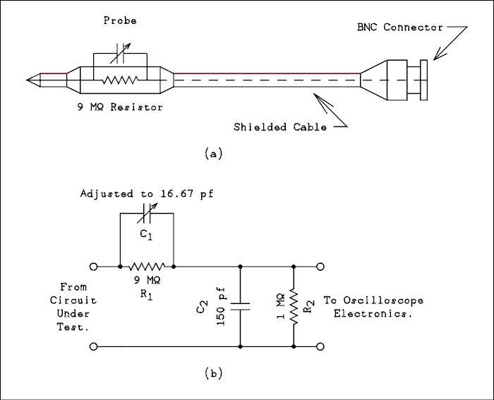
Figure 2.2 Schematic of X10 Probe.
For a verbal description click here.
It is possible to increase the input resistance and decrease the input capacitance of a scope by giving up some sensitivity. Figure 2.2(a) shows a drawing of a times ten probe and 2.2(b) the schematic diagram. The scope is presumed to have an input impedance of 1 M ohms resistor in parallel with a 30 pf capacitor. The variable capacitor in parallel with the 9 Megohm resistor would be physically inside the probe.The frequency response of the circuit will be flat if
R1 C1 = R2 C2 (2.3) is satisfied. Where R1 is the 9 Megohm resistor in the probe tip, C1 is the variable capacitor in the probe tip, R2 is the 1 M ohms resistor which represents the input resistance of the scope and C2 is the sum of the cable capacitance and the input capacitance of the scope 150 pf. If we solve equation 2.3 for C1 and plug in all known values, we have C1 = (1 M ohms x 150 pf)/(9 M ohms) = 16.7 pf. The effective input capacitance is C1 in series with C2 which is 15 pf. That's a lot better.The effective input resistance is R1 in series with R2 which is 10 M ohms. That's also a lot better.
To sum it all up, by using a times ten probe the input resistance goes up by a factor of ten and the input capacitance goes down by a factor of ten. The voltage applied to the input of the scope is 1/10 of that applied to the probe tip.
Example 2.18.
The following information is obtained using an oscilloscope. Peak to peak voltage is 125 millivolts and period is 22 milliseconds. A times ten probe is being used. What are the actual voltage and period.Solution:
The voltage is ten times what is measured, 125 mv x 10 = 1.25 volts. The times ten probe has no effect on the period measurement.Adjusting the Times Ten Probe.
Before a times ten probe is used it must be adjusted to match the particular scope that is in use. As indicated in figure 2.2 the variable capacitor is in the probe tip but in some probes the adjustment is at the scope end of the probe cable. This is accomplished by making the capacitor at the probe tip a fixed value and a little larger than the theoretical value and placing a variable capacitor in parallel with the scope and cable capacitance, C2, placing it more conveniently at the scope end. Wherever it is it must be adjusted.All oscilloscopes have a square-wave output which has been put there for exactly this purpose. If the probe has a switch to select X1 (times one) or X10 (times ten), be sure it is in the X10 position. Connect the probe tip to the square-wave output and adjust the controls on the scope to obtain a stable display of the square-wave.
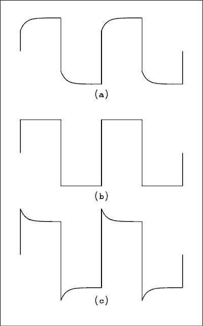
Figure 2.3 Square-wave for (a) undercompensated probe
(b) properly compensated probe and
(c) overcompensated probe.
For a verbal description click here.
If a screwdriver is required to adjust the probe, use a plastic one. Refer to figure 2.3. Figure 2.3a shows the condition of not enough capacitance, under compensation, while figure 2.3c shows the condition of too much capacitance, overcompensation. Figure 2.3b is just right, correct compensation. If it is not readily apparent how to adjust the probe, consult the instruction manual.AC, DC and Ground.
All but the least expensive scopes have a switch located near the input connector which is labeled "AC DC GND" for AC, DC and ground.When this switch is set to the AC position, a capacitor is connected in series with the input to the scope. This capacitor will block DC from the input but will pass AC. The size of the capacitor is usually chosen so that the low frequency limit will be about 2 hertz. The upper frequency limit is set by the amplifiers in the scope and is uneffected by the setting of the switch.
In the DC position the scope responds to both AC and DC. The capacitor mentioned above is shorted out. The response of the scope is from DC (zero frequency) to the upper frequency limit of the scope. This makes it possible to use the scope to measure DC voltage the same as you would with a voltmeter.
When the switch is set to the GND (ground) position the input to the vertical amplifier is grounded. The input resistance (as "seen" by the circuit under test) is not affected so that the circuit under test will not be damaged. In many measurements, especially those involving DC, it is essential to know where the trace would be if the input voltage to the scope were zero. Instead of disconnecting the probe, all that is necessary is to flip the input switch to the GND position, note the position of the trace (or use the positioning control to put it where you want it) and then flip the input switch back to DC or AC.
Example 2.19.
Figure 2.4 represents the display of a DC + AC voltage on an oscilloscope. When the input switch is set to ground, the trace is positioned one division up from the bottom of the screen, or at Y = -3 divisions. In figure 2.4a the scope operator has used the horizontal positioning control to set the most positive peak on the line of hash marks. In figure 2.4b the horizontal positioning control has been adjusted to put the least positive peak on the line of hash marks. This is what you would do if you were in a laboratory instead of reading a book. The settings of the scope controls are as follows: input switch to DC, Vertical range to 0.2 v/div and sweep range to 5 ms/div. A times ten probe is being used. What is: (a) the peak to peak voltage; (b) the voltage of the most positive peak; (c) the voltage of the least positive peak; and (d) the period of the wave?
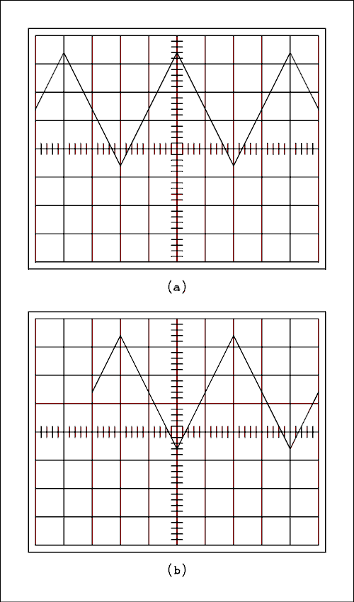
Figure 2.4 Scope screens for Example 2.19.
For a verbal description click here.
Solution:
The only difference between figures 2.4a and 2.4b is that the horizontal positioning control has been changed. Figure 2.4a reveals that the most positive peak is 3.4 divisions above the center line and figure 2.4b reveals that the least positive peak is 0.6 divisions below the center line.(a) The peak to peak distance of 3.4 div - (-0.6 div) = 4 divisions. 4 div x 0.2 v/div x 10 = 8 volts peak to peak.
(b) The voltage of the most positive peak is measured from the zero voltage line. As given, the zero volt line is one division up from the bottom of the screen or 3 divisions below the center line. The distance between zero volts and the most positive peak is 3.4 div - (-3 div) = 6.4 divisions. 6.4 div x 0.2 v/div x 10 = 12.8 volts.
(c) The distance between zero volts and the least positive peak is -0.6 div -(-3 div) = 2.4 divisions. 2.4 div x 0.2 v/div x 10 = 4.8 volts.
(d) We must use center line crossings in order to have the hash marks to read. Selecting two successive positive going center line crossings we have the wavelength as 4 divisions. The period is 4 div x 5 ms/div = 20 ms. The times ten probe has no effect on the time measurement.
Getting Best Accuracy.
Using modern oscilloscopes with some care it is possible to obtain accuracy equivalent to that of an analog meter. There are certain things you can do to maximize the accuracy of the measurement.For voltage and period measurements keep the vertical deflection large. The large divisions are subdivided by the hash marks into 5 subdivisions. It is possible to mentally insert 4 sub-subdivisions between the hash marks. That means that the best resolution is 1/20 of a large division. That is the ideal case. In actual practice it is more likely that the best resolution is 1/10 of a large division.
If you only have a vertical deflection of one large division, the typical accuracy is about (0.1 div)/(1 div) x 100% = 10%. If the vertical deflection is about 6 large divisions the typical accuracy is about (0.1 div)/(6 div) x 100% = 1.7%. 2% accuracy is about the best to be expected.
For period measurements have several cycles on the screen. Also, measure from zero crossing to zero crossing, not peak to peak. The horizontal position of the rounded peak of a sine wave cannot be determined with any accuracy.
If the vertical deflection is large and there are several cycles on the screen, the zero-crossings will be almost vertical. Suppose you tried to measure the period from one positive peak to the next. You would be trying to determine the exact point of tangency of the curved peak of the wave to the scale, not an easy thing to do. When an almost vertical line crosses a horizontal scale it is easier to determine the exact point where the crossing takes place.
If you measure the time for four or five cycles, the accuracy of the measurement will be improved. If you measure the period of just one cycle, the distance will be rather small and the same argument will apply as for the vertical deflection. Measuring over several cycles increases the distance of the measurement and increases the accuracy.
Trigger Modes.
In olden days the horizontal sweep was generated by an oscillator with a sawtooth wave form. To get a stationary pattern on the screen it was necessary to synchronize the sweep oscillator with the input signal. Today's scopes use a triggered sweep instead of a synchronized sawtooth oscillator.The key difference is that an oscillator keeps on running at approximately the same frequency even in the absence of an input signal. A triggered sweep begins when a trigger pulse is received, completes one cycle and then waits for the next trigger pulse before beginning the next cycle. If the trigger pulses stop, the sweep stops.
The "auto" mode is to keep a visible trace on the screen in the absence of an input signal. If you put the input switch in the GND position, you want the trace to be on the screen so you can see where it is. A special circuit senses that there are no trigger pulses and generates artificial trigger pulses. These pulses are removed when real pulses are present. Like any other automatic circuit it can sometimes get confused and cause the pattern on the screen to be unstable. When this happens, you should switch out of the auto mode. If you want to use the GND position on the input switch, you will have to put the trigger back into the auto mode. Someday it will occur to some engineer (who can do something about it) to cause the trigger circuits to go into the auto mode whenever the input switch is placed in the GND position.
The Slope switch selects whether the sweep will trigger on the positive going or negative going slope of the input wave.
The level control sets the voltage level at which the sweep will begin.
Trigger coupling modes come in a wide variety of shapes and sizes. A few of them are DC, AC slow, AC fast, AC lf, AC lf rej, (reject), TV, TVh, TVv, TVl and TVf. DC is a full spectrum coupling. It is used for slowly changing, infrequently occurring or DC restored video signals. AC slow and AC lf are for low frequency sine or sine like waves. AC fast and AC lf rej are for square-waves, pulses or high frequency sine waves. TV is a general television trigger mode. In some scopes the horizontal or vertical sync pulses are selected depending on the setting of the sweep range switch. TV h (horizontal) and TV l (line) select the horizontal sync pulses from the TV signal to be fed to the trigger circuits. TV v (vertical) and TV f (frame of field) select the vertical sync pulses.
For complete information you should consult the instruction manual for the particular scope you are using.
Measuring Current and Resistance Using a Scope.
Earlier it was mentioned in passing that it is possible to measure current and resistance using a scope. How is that possible? A decade resistance box would come in handy but all you really need are a few precision resistors.Measuring current is easy and maybe some of you have figured that one out already. Simply place a resistor, say one ohm, in parallel with the input of the scope. The ranges on the vertical range switch become current ranges. For example, using a 1 ohm resistor the 100 mV/div range becomes 100 mA/div. The resistor should have sufficient wattage rating to carry the current being measured. Also remember that if the voltage drop becomes too great, you will perturb the circuit under test and the current measurement will be in error.
Measuring resistance requires a bit more ingenuity. All scopes have a square-wave signal output for compensating the probe. This output is used in the circuit of figure 2.5. Since one side of the circuit is connected to the scope's own ground it is not possible to measure the voltage across each resistor individually. Measure the voltage across the reference resistor RR and then measure the voltage across the series combination of RR and RX. This last voltage is of course the output voltage of the square-wave output. For best accuracy the voltage across the reference resistor should be about half of the square-wave output. The unknown resistance is given by
RX = RR (VS - VR)/VR (2.4) where RX is the unknown resistance, RR is a known reference resistor, VS is the voltage of the square-wave source and VR is the measured voltage across the reference resistor.
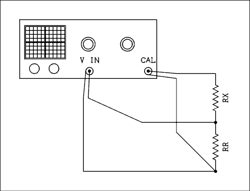
Figure 2.5 Resistance Measurement with an Oscilloscope.
For a verbal description click here.
Back to Fun with Transistors.
Back to Fun with Tubes.
Back to Table of Contents.
Back to top.
2.6.1 The Digital Storage Oscilloscope (DSO).
Time and technology march on. These days you only see cathode ray oscilloscopes at ham fests and university and industrial yard sales. Storing a very low frequency or single occurrence wave in a CRT took some very special structures inside the tube. For all the money that a university or industry research lab had to pay for them they didn't work very well. In a DSO the wave is digitized and stored in memory and read out to be displayed on the screen. It doesn't make any difference if one cycle of a wave takes 10 ns, 1 μs, 1ms, 1 s, 10 seconds, a minute, or an hour. Once the wave has been read into memory it appears on the screen as a wave without any hint of flicker. If the wave only happens once no matter how long or short the period it can be displayed for as long as the operator needs to make measurements. Of course the contents of the memory can be transferred to a thumb drive and from there to a computer. Now there is no need for a stock of expensive film and for the Polaroid camera mounted on the scope.Operational differences.
Designers of DSOs grew up with analog scopes and they naturally gravitate toward making the controls operate the same as before. A few differences have emerged which make operation more flexible and easier.The trigger point has been moved from the left edge of the screen to the center. You don't need to adjust the control on the edge of a hair trigger to be sure you are seeing the entire rise of a square or pulse wave. Just turn up the sweep speed and the rise will sit right there in the center of the screen as it stretches out for easy measurement.
Range Settings are on the screen rather than on the panel. In fact if you start turning any knob on a DSO you will never come to a stop. None of the controls are detented wafer switches or potentiometers (pots). They are all shaft encoders. The range settings are displayed on the screen because that is the only way to show them. This was done in a few models in the analog era and it worked pretty well.
Cursors for more accurate measurement are a common feature of DSOs. This was also tried in the analog era but they weren't very successful. All they did was to make the calibration procedure longer and more complicated. Cursors can be lined up with traces with better accuracy than a trace by itself can be read. And of course the cursors have digital readouts.
Direct digital readout of commonly performed scope measurements are provided by firmware built into the scope. Some of these are; peak to peak, RMS, average, rise and fall time, pulse width, frequency, period, and even fast Fourier transform. Scopes that have just the minimum of these features essentially give you a scope, DMM, and frequency counter all in one box. Full featured scopes are more like having a scope and computer in the same box. The screen can get rather busy with all of these digital readouts on it which is why advanced features such as cursors and direct measurement can be switched off if they are not needed at the moment.
The input resistance and units of measurement can be changed in some high end models. The input resistance, impedance to some, can be switched between 1 meg ohm and 50 ohms. Any communications engineer or technician will immediately understand the usefulness of that feature alone. The units of measurement can also be switched between voltage and current. I'll bet that power measurement isn't far off if not already here. I have yet to see one with the power feature.
Four function math involving the two traces is also a feature of a DSO. The most that could be managed in the bad old days was add and subtract. Digital technology has added multiply and divide. Below you see what happens when you multiply two triangular waves that have a 90 degree phase difference.

Figure 2.5.1 Screen Shot Showing Multiply Function.
The text below is a rather good verbal description of the picture.
This picture gives me a chance to point out the main features of a DSO. At the right you see at the top a frequency readout that has frequency counter accuracy. Below that you see that the sample rate is 2.50 mega samples/second. For the next line your guess is as good as mine about Curr 7kbts. I haven't figured out all there is to know about this DSO thing. Below that is the trigger status display. The sweep is being triggered from channel 1 on the positive going edge with DC coupling. The trigger level is set to 0. This is zero relative to the trace which is the trigger source. Regardless of vertical position, zero is the level you get when the input selector is set to ground.Below that you see that channels 1 and 2 are set to the 500 mV/div range with DC coupling and 1 Meg ohm input impedance. The channel 1 offset is 500 mV while the channel 2 offset is -500 mV. Channel 2 has the band width limit turned on while channel 1 does not. When on, the bandwidth of the channel is 20 MHz. This is a 200 MHz scope.
The yellow triangle at the right of the grid is the trigger level setting. The blue triangle at the top center of the screen is the trigger delay. The selected trace triggers at the intersection of the two lines drawn from the symbols. Both the trigger level and the delay are adjustable. The delay takes the place of the horizontal position control from analog scopes. In fact on this particular scope the control is called "position". On other DSOs it may be called delay or trigger delay.
The sweep speed is displayed just to the left of the word delay.
On the left edge of the grid you see three icons with characters inside them. The yellow one has a 1, white has an M and purple has a 2. These indicate the zero points of channel 1, the results of the math operation and channel 2 respectively. The math has its own positioning and range switch. On this scope the range switch is not labeled because it doubles as a control for the digital option which I do not have installed. There are only two ways of knowing this. Trial and error or reading the manual. Other scopes may be labeled a little better.
Along the bottom of the screen you see the soft key menu for the math function. There are hard keys to the right of the screen that select different menus. When a soft key is pressed one of two things happens. If there are only two alternatives the one that is currently selected changes to the other one. If there are 3 or more alternatives a pop up menu appears showing them. You can see that the operation is set to * (multiply), source A to channel 1, source B to channel 2, and invert to off. The empty space indicates that there are two more soft keys which are not used on this menu.
If you press the hard key for channel 1 or 2 the menu for that channel comes up. Some of the items are familiar and some are not. The first one is for selecting DC or AC coupling and ground. The next is bandwidth limit on/off. Next is adjust course/fine. This takes the place of that Vernier control that was concentric with the range switch on analog scopes. The fine setting of this item causes the range switch to change in tiny increments. So you can set a square wave amplitude to the dotted lines and easily identify the 10 and 90 % points on the rise and fall. Next is the probe selection key which doesn't just have X1 and X10 but values ranging from X0.1 to X10,000 set in a 1, 2, 5, sequence. Next is the 1MΩ/50Ω selector. The last key brings up the second page. First on the second page is V/A. Next is Deskew and has a number in nano seconds that can be changed by rotating a multifunction knob. I don't really understand this one. And finally is invert on/off. Oh yes, there is another key that brings back the first page.
When I was exposed to my first DSO I was able to puzzle it out with only a little help from the manual. If you find yourself employed by a research lab that is part of a large university or large company it is a virtual certainty that you will find a DSO on your workbench. The only places you are likely to find an analog scope is in the labs of a small college or high school in a not poor but not rich school district.
Low end DSOs really don't work very well. Given the choice I would rather have an analog scope from the end of the analog era than one of these poor excuses for a DSO. You would probably see an analog scope in a TV repair shop if they still existed, but they don't. The manufacturers have made TVs unrepairable and no one tries. Buy it, use it, and when a 2 cent resistor fails throw it away and buy a new one. That benefits the manufacturer and the big chain stores that sell the sets but does harm to the consumer and the environment.
Back to Fun with Transistors.
Back to Fun with Tubes.
Back to Table of Contents.
Back to top.
2.7 The Signal Tracer.
A signal tracer is an old instrument that was used primarily to troubleshoot radios back in the tube era. If you are interested in restoring Antique radios I strongly recommend that you buy or build one. The basic instrument was an audio amplifier and a speaker built into an instrument box. Some units such as the Heathkit T-4 also contained an eye tube. This seems to me to be just to dress up the instrument and serves little practical purpose. They are old enough to be considered antiques and if you buy one off eBay you will likely pay too much. Even if you have to buy all new parts you will likely pay less to build your own. Below is a practical circuit.
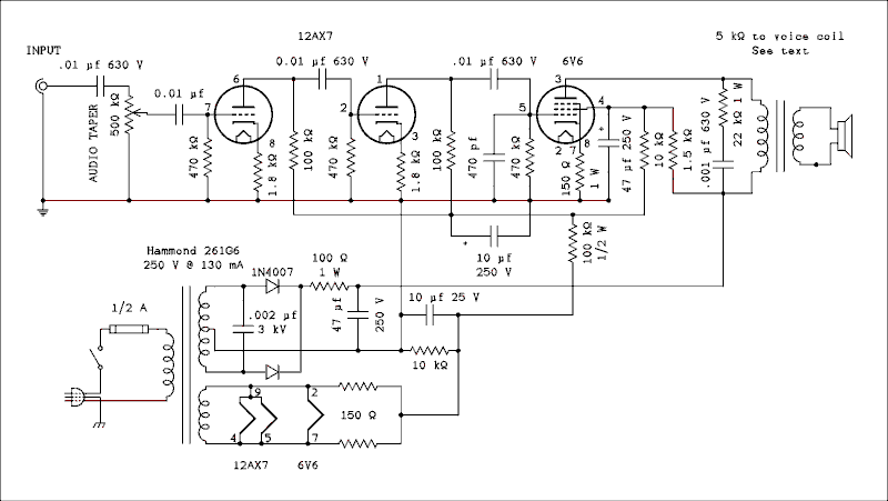
Figure 2.6 Signal Tracer.
For a verbal description click here.
The output transformer is a standard 5 k ohm to voice coil and may be scavenged from an all American 5 if desired. The power transformer has a higher current rating than needed but one just above it on the AES page which had a lower current range costs a dollar more. If desired you could use the extra current capacity to power experimental circuits.If you prefer you can substitute a 6AQ5 for the 6V6. No component changes are necessary to change the tube. Remember that the pin numbers are different.
Oscillation.
It is very likely that this circuit will oscillate when there is nothing connected to the input and the volume control is turned up all the way. The 470 pf cap from the grid of the 6V6 to ground is meant to help but it won't prevent it completely. It will insure that it will be audible. My Heathkit T-4 and the amplifier in the combo power supply and amplifier do. It can be prevented by using a lot of shielding between the output tube and transformer and the 12AX7. It really doesn't hurt anything though.As you can see this is nothing more than an audio amplifier with a whole lot of gain. It is useful for tracing signals through the audio section of a radio. A shielded probe should be used and a scope probe is a very good choice. Get one that has a times 1/times 10 switch on it. Of course you will have to mount a BNC connector on the tracer to make use of a scope probe.
Radio Frequencies and Intermediate Frequencies.
So how does one trace signals through the RF and IF stages of a radio? Here is how.

Figure 2.7 RF Probe for Signal Tracer.
For a verbal description click here.
You can use 1N4148 diodes if you want but performance will be much improved if you use Schottky diodes. I believe 1N6263 is the best choice. The probe will not perform quite as well with germanium diodes. If you can get them or their equivalents 1N270 or 1N933 diodes will be better than silicon. If you can't get those 1N34A diodes will work just fine. The first capacitor in line should have a voltage rating of 500 volts because it will regularly come into contact with B+ voltages.This probe has the advantage over the one supplied with the Heathkit T-4. It filters out low frequencies and responds only to frequencies higher than 50 kHz. In a departure from the usual quality Heath engineering the T-4 was supplied with a simple probe that didn't work very well. The manual admits this by saying that the probe should not be connected to the plate of a tube because all the operator will hear is 60 Hz hum from the power supply. Using this probe that will not be a problem.
The probe should be shielded to avoid the effects of hand capacitance but the metal shield should be covered with some kind of insulating material. It is not safe to work on a radio that has lethal voltages in it while holding a grounded probe in your hand.
Another use for the probe is to measure RF voltages. The DC output of the probe is very close to the peak to peak value of the input wave. If it is a good sine wave the RMS value of the wave is Vdc / (2 Square root of 2).
Also, do not be tempted to leave out the power transformer! Some of the radios you will be working on will be of the line connected chassis type and having two pieces of hot chassis equipment on your workbench is a catastrophe waiting to happen.
Back to Fun with Transistors.
Back to Fun with Tubes.
Back to Table of Contents.
Back to top.
2.8 Miscellaneous Test Equipment.
There are many different pieces of test equipment. Some are not well known. Some pieces of test equipment are designed to test one particular make and model of apparatus. These are usually referred to as "test sets" rather than test instruments. Test sets cannot be covered in a book such as this. They are issued to franchised service agencies and field service persons. Training in their use comes from the manufacturer.Signal Sources.
Signal sources are used in the signal substitution or signal injection methods of testing to be covered in chapter 4 of this book.There are three general categories of signal sources (more often called signal generators). They are 1) audio frequency, 2) radio frequency, and 3) pulse generators.
Audio frequency generators come in a wide variety of makes and models. The minimum acceptable frequency range is 20 to 20,000 hertz but most technicians prefer a range of 5 hertz to 1 megahertz. Generators are available which provide low distortion sine waves (.05% or less). The most familiar, however, is the function generator which provides sine, square and triangular waves. The distortion of the sine wave is usually in the range of 0.3% to 1%. A typical frequency range is from 1 hertz to 2 megahertz. The Thevenin output resistance of these generators is usually 50 ohms. Some function generators also provide outputs which are compatible with digital logic circuits. For details on operating procedure consult the instruction manual for the particular make and model you are using.
Radio frequency generators are further subdivided by the part of the radio spectrum they cover. For example a Hewlett-Packard model 606A is called an HF (high frequency) signal generator. It covers the range 50 kHz to 65 MHz. Granted, the HF spectrum is from 3 to 30 MHz but they didn't want to call it a "most of LF, MF, HF and part of VHF signal generator". As you can see from this example there is considerable overlap of AF (audio frequency) and RF (radio frequency) generators.
The one feature which distinguishes an RF generator from an AF generator is calibrated output voltage and power level. All RF generators worthy of the name use a combination of an output level meter and a well-calibrated attenuator to provide an output level which is known. The level is measured across a 50 ohm load and usually ranges from 0.1 microvolts to about 1 volt. Upper limits vary from one model to the next and can range from 0.2 volts to 3 volts.
Some high-priced AF generators may also have calibrated output levels, the minimum level usually about 1 millivolt. Only an RF generator will have a minimum output of 0.1 microvolts.
Pulse generators are used to stimulate logic circuits. They have outputs which are compatible with various integrated logic families such as TTL (transistor transistor logic), CMOS (complementary metal oxide semiconductor), ECL (emitter coupled logic) and others.
The pulse width and frequency are independently adjustable. There are frequently provisions for external triggering or triggering from the operation of a pushbutton switch.
Logic Probe.
A logic probe looks simple but can be quite complex. In general it has two indicator lights, one for a low logic level and the other for a high logic level. You might think that one light would do but if no lights are on, the probe is indicating an open circuit on its input.If the logic probe is testing a pulse train of say 20 PPS (pulses per second) or higher, the lights will flash off and on too fast for the eye to perceive as flashes and they will look as if they are on continuously. A good logic probe will contain circuits which force the lights to flash slowly enough to be perceived as flashes.
Thus you have an unambiguous indication of logic low, logic high, open circuit or pulse train.
A logic probe must be compatible with the logic family with which it is being used.
Continuity Tester.
A continuity tester is a device which gives an indication when the resistance between its test leads falls below some preset value such as 100 ohms. The indication can be either visual or oral or both.Many logic probes incorporate a continuity test mode.
Continuity testers are good for testing fuses, switches, line cords and even diodes. Although they are employed primarily by technicians who work on power or telephone circuits they can be a handy tool for the electronics technician as well.
Test Lamp.
A test lamp has the advantage over a voltmeter of being smaller and much less hassle to use. If the user desires to know if the voltage is present or absent, it is just what the doctor ordered.In its most common form a test lamp is a neon lamp with a current limiting resistor in series with it. It may be housed in a small plastic cylinder and be equipped with a pocket clip. It will have two test leads emerging from it. The test lamp is used to check for the presence of AC line voltage.
You can also make your own test lamp. A six volt lamp makes an excellent quick tester for the presence of five volt power in a computer circuit.
Clamp On AC Ammeter.
There is a class of AC ammeters which requires no direct connection to the circuit under test. They sense the magnetic field around a wire carrying AC. This magnetic field is directly proportional to the amount of current in the wire.These meters have a spring loaded clamp which can be opened by squeezing a handle on the meter. The clamp is opened and allowed to close around, not on, the wire in which the current is to be measured.
The clamp must be placed around one wire. If you put the clamp around a lamp cord (two wires) the meter will read zero. The reason for this is each wire in the lamp cord is carrying current in the opposite direction to the other one. Because this is a series circuit, the current in each wire has the same magnitude. The two equal and opposite currents cancel each other out and there is no reading on the meter.
These meters are often called "amprobes" but Amprobe is a registered trademark.
Non Contact Voltage indicators.
This is a very small device which is a little fatter than a fountain pen and just slightly shorter. There is no metal on the outside. It has a plastic tip that is the correct size and shape to fit into either of the prong slots in a standard 120 VAC socket. When the spring loaded button on the side is pressed it emits a single beep. If the tip is inserted into the hot slot, shorter of the two, and the button is pressed it will emit a series of beeps for as long as the button is held and the tip remains in the slot. If there is no power to the outlet or the tip is inserted into the neutral slot it will emit a single beep when the button is pressed. It will also beep repeatedly if the tip is brought close to a hot wire in an electrical panel or any other place where electrical wiring is found. It will even beep on a lamp cord if it is close to the hot wire of the two. It will only detect AC not DC. It is used to make sure the power is off before removing safety covers. The single beep is to reassure the user that the battery is not run down. If there is no beep upon pressing the button do not bet your life on its silence.Back to Fun with Transistors.
Back to Fun with Tubes.
Back to Table of Contents.
Back to top.
2.9 Instruction Manuals.
It is a common joke among technicians and engineers that, "When all else fails, read the instruction manual." This expresses the reluctance of most technical people to admit that they don't know something. There are, however, times when you should consult the instruction manual.If you have encountered a familiar piece of equipment such as an oscilloscope, you may feel as if you know how to use a scope and don't need the manual. But if it is one of those new digital models (with no knobs, just push buttons) you will likely be sufficiently stumped to need some help.
If the equipment is unfamiliar you should by all means "read the book". There are only a few combinations of control settings which will work and an infinite number which will not work. The odds of hitting a working combination by random turning of knobs are vanishingly small.
Don't be ashamed to "read the book". There's no shame in that. No one was born all knowing.
Back to Fun with Transistors.
Back to Fun with Tubes.
Back to Table of Contents.
Back to top.