
Voxson Model 762 Converter Section Only.
For a verbal description click here.
The All Japanese Six Radio.
The Converter.
The first transistor in an All Japanese Six converts the frequency of the incoming station to the Intermediate Frequency (IF). In the early years of radio this conversion was known as heterodyning. The principle of heterodyning had been developed by Edwin Armstrong in the 19 teens and an early version was offered to the public as early as 1919 but it really didn't catch on in the consumer market until the late 1920s. The AJ 6 is known as a super heterodyne receiver.Here are partial diagrams of the two AJ 6 radios we are studying as of this lesson.
Voxson Model 762 Converter Section Only.
For a verbal description click here.

Sanyo Super-Six Converter Section Only.
For a verbal description click here.
The symbol on the left of the figure is the ferrite antenna. This consists of two coils wound on a ferrite block or rod as shown in the picture below. These antennas were usually visible to the user when the back of the radio was removed to change the 9 volt battery.
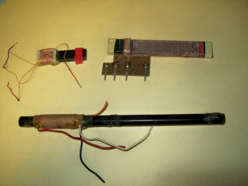
For a verbal description click here.
The one at the upper left is one that was removed from a 6 transistor pocket radio, the one on the upper right is likely to have been found in a slightly larger portable, while the one at the bottom may have been used in a table radio or large, relatively speaking, portable. For purposes of scaling the longest one is 7 inches.Ferrite material is finely powdered iron mixed with a ceramic like material. The small particles permit it to be magnetized at radio frequencies without shorting out the electric field of the radio signal. The magnetic field from the radio station tower passes through the ferrite material and the field is concentrated more than it would be in air. The current induced in the coil is stronger than it would be in a coil with an air core. The variable capacitor tunes the coil to the frequency of the desired station and that station's signal is the strongest one induced in the coil, all other things being equal. The resonant coil may appear to be doing nothing but the resonant effect reinforces the magnetic field in the ferrite core and it is much larger than it would be without the resonant effect. The upper coil has a current induced in it by the magnetic field and this current is sent to the base of the converter transistor.
You might assume that the rest of the radio has tuned circuits set to the frequency of the station you want to listen to. That's exactly what radios did before about 1930 (although they didn't have built in antennas back then). These were known as TRF for Tuned Radio Frequency receivers. If you want more information on TRF circuits follow this link then use your back button to return here.
The coil serves both as a means to pick the radio signal out of the air and a tuned circuit that begins the process of selecting the one station out of many that you want to listen to. The signal from the antenna is fed to the base of Q1. This transistor is an oscillator and also a mixer that converts the incoming signal to the intermediate frequency.
The Principle of Heterodyning.
Heterodyning is more commonly known as "mixing", "conversion" or "modulation". OK; but what is it? If you combine two frequencies in a device known as a "mixer", "converter" or "modulator" you get two new frequencies. These new frequencies are the sum and difference of the two original frequencies. For example if you combine 5 MHz and 6 MHz in a mixer you get the two original frequencies and in addition you get 1 MHz and 11 MHz. If you combine 650 kHz and 1105 kHz you get 455 kHz, 650 kHz, 1105 kHz and 1755 kHz.There are some types of mixers in which the original signals are canceled out and ONLY the sum and difference frequencies appear in the output. These devices are called "doubly balanced mixers" or DBMs for short. Other pages will get to them in time. But for now we are discussing mixers in which the original two signals appear in the output along with the sum and difference frequencies.
So What is a Mixer?
Well, it's any nonlinear device. A nonlinear device is anything that has a graph that isn't a straight line. A diode, either vacuum or semiconductor makes an excellent mixer. A tube or transistor which is being driven into overload is another excellent mixer. The balanced variety consists of combinations of diodes and transformers, or transistors (usually in an integrated circuit).The Superhet Receiver.
In a TRF (tuned radio frequency) receiver mentioned above all tuned circuits are tuned to the frequency of the incoming station. There are lots of reasons not to employ this method of reception. A radio works much better if the incoming station frequency can be changed to a constant frequency that is not tunable by the user and remains stable for many decades.For more details on comparisons of TRF to super heterodyne receivers see the Fun with Tubes website and use your back button to return here. Some of the text at that destination is the same as what is here but many of the points are discussed in greater detail.
Are you ahead of me? Yes. The mixer is how the frequency can be changed. The frequency we generate to combine with the incoming station is produced within our own circuitry so it is local. It is called the "local oscillator". Let's say we have constructed a fixed tuned amplifier at a frequency of 455 kHz. (That's the almost universally used frequency for this amplifier. So if we want to listen to a station on 780 kHz we must tune our local oscillator to 780 kHz + 455 kHz = 1235 kHz. The 1235 kHz local oscillator combines with the incoming station at 780 to produce two new frequencies at 455 kHz and 2015 kHz. The tuned circuits select the frequency at 455 kHz and reject all others. The frequency of 455 kHz is in-between the station's frequency and the audio frequencies so it is called the "Intermediate Frequency" or just IF for short.
To say "the IF frequency" is to be redundant along with PIN number, IBM machine, SAT test, SEC conference, HIV virus, and thousands of others you can hear all the time even on network radio and TV.Image Frequencies.
Suppose you live in Cincinnati so you have a strong local station on 1530 kHz. (It used to be WCKY; I don't know if it has changed. I haven't heard it in a long time because it skips over me here in BG KY.) Well, suppose you would like to listen to an out of town station which is operating on 620 kHz. You tune your local oscillator to 620 + 455 = 1075 kHz. What do you hear? Well, WCKY on 1530 is also there and combines with your local oscillator on 1075 to produce a difference frequency of 1530 - 1075 = 455 kHz. OOPS! That's the main drawback to a Superhet receiver. It receives two frequencies simultaneously at the same time. It's up to the antenna coil which is tuned to 620 kHz to reject the strong signal on 1530 so you can listen to the station you want to hear. A really good AM radio will have an amplifier stage before the mixer, called the "RF Amplifier" or "RF Stage" with two tuned circuits to make sure you are only listening to one station at a time.The Transistor Converter.
The best way to build a transistorized superhet would be to use one transistor as the oscillator and another as the mixer. Serious communications receivers are designed this way. But the AJ6 must cut every corner possible to make it as inexpensive as possible. A single transistor serves as oscillator and mixer. We have already seen how the incoming signal from the ferrite antenna is injected into the base of the converter.The two converter circuits are repeated here to make comparison easier.

Both Converter Circuits Shown Side by Side.
For a verbal description click here.
The base of the transistor is biased by the resistor which goes from -9 volts to the low end of the base winding of the antenna and the other resistor which goes from the low end of the base winding to ground. The collector current is set by the resistor which goes from the emitter to ground. Collector current passes from the -9 volt point through the bottom few turns of the IF transformer primary then through the tickler winding on the oscillator coil to the collector.The coil and variable capacitor on the right make up the oscillator tuned circuit. Energy is taken from the collector by the tickler coil which is just a few turns. This coil is magnetically coupled to the resonant coil which has a tap that is not in the center. It is somewhere in the middle between the ends so I will refer to it as the mid-tap. The lower end of the resonant coil is grounded. The mid-tap is a few turns up from the grounded end of the resonant coil.
To this point both circuits are the same. In the Voxson circuit feedback for the oscillator is coupled from the mid-tap through a 0.01 uf capacitor to the emitter of Q1. The lower end of the base winding on the antenna is bypassed to ground by another 0.01 uf capacitor.
In the Sanyo circuit feedback from the mid-tap of the oscillator coil is coupled to the low end of the base winding on the antenna by a 0.003 uf capacitor. There is no bypass capacitor to ground at this point. The emitter is bypassed to ground through a 0.01 uf capacitor.
An oscillator is nothing more than an amplifier with positive feedback through a frequency determining circuit that will control the frequency at which the circuit oscillates. The Voxson circuit uses a grounded base oscillator. When signal is injected into the emitter the transistor does NOT invert the signal. The Sanyo circuit employs a grounded emitter oscillator. When signal is injected at the base the transistor inverts the signal. If the same oscillator coil were to be used for both circuits the tickler winding would have to be reversed in one circuit as compared to the other to maintain positive feedback and oscillation.
It seems unlikely that the same coil could be used in both circuits. The input impedance at the emitter is much lower than that at the base. For the Voxson circuit the tap on the coil would have to be much closer to the bottom to match the lower impedance at the emitter. This question will be resolved on a soon to be added page in which I will construct a 6 transistor radio using parts purchased from Radio Shack before they became a phone store.
An oscillating transistor is being driven from saturation to cutoff which qualifies it as a nonlinear device. The incoming signal from the radio station combines with the oscillations to produce the sum and difference signals required to qualify this circuit as a converter. The 455 kHz difference signal between the station's frequency and the local oscillator is selected by the fixed tuned IF transformer which is connected in the collector of Q1. The collector of the transistor represents a low impedance and would load the tuned circuit and lower its Q to a point where it would not do a good job of rejecting station's signals on nearby channels. Tapping the collector down on the coil allows a sufficiently high Q to permit stations to be heard one at a time. The small winding in the IF transformer matches the impedance of the base of the first IF amplifier transistor.
General Information.
The Converter.
The IF (Intermediate Frequency) Amplifier.
The Detector and AGC/AVC (Automatic Gain Control/Automatic Volume Control).
The Audio Amplifier Section.
Conclusion.
This page last updated April 25, 2011.