|
Specifications
Explanation
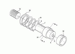
Each inner cylinder has a threaded receptacle on one end, which receives the lug from the vehicle drum or hub, and a drive opening on the other end, which receives the drive anvil of an impact wrench, usually one-half (1/2) inch in size. This eliminates the loss of the lug nuts and because of the outward movement of the inner cylinder facilitates disengagement of the impact wrench.
Background of the InventionThe present invention relates to the field of automotive wheels, particularly the disc portion hereinafter referred to as vehicle rims. More particularly, it relates to a combination vehicle rim and lug nut assembly to facilitate the removal and remounting of tires on an automobile or similar vehicle wherein the disengagement of an impact type lug wrench normally utilized for such procedures is simplified and accelerated. Field of the InventionIn the field of the present invention, the users of vehicles often have occasion to change a tire and rim with the concurrent problems of loss of lug nuts in some circumstances and the jamming of an impact type or other lug wrench in other circumstances. Nowhere is this more critical than in the field of auto racing wherein the speed of changing of tires and rims has a direct effect on the outcome of many races. Often, an otherwise speedy automotive crew or pit crew as they are often called, is stymied in its efforts to speed a car along its way by the unforeseen jamming of a lug nut inside the socket of an impact wrench. Also, rapid alignment of the rim with its counterpart on the vehicle drum or hub is also a highly desired result. A vehicle rim which can be quickly mounted and which facilitates the removal of the anvil of the impact wrench from a lug nut is still needed in the art.
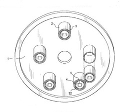
These and other objects and advantages are now achieved by the apparatus of the present invention, which provides a combination wheel rim and lug nut assembly wherein a rim, having an inside and outside face has a series of tubular extensions mounted equidistantly around the circumference of the rim, usually five (5) in number. Mounted in each tubular extension is a two part cylindrical member. The outer cylindrical portion is fixedly mounted to the tubular extension and the inner cylindrical member is free to rotate and slide longitudinally within the outer cylinder. A series of linear bearings facilitate this motion and are interdisposed between the two cylinders. The inner cylinder has an inward end which has an aperture defined along its axis which is threaded to accommodate the lug bolt in the drum or hub and the outward end has a drive opening, usually one-half inch (1/2"), defined within it to receive the anvil of the impact wrench which can be therein engaged. A helical spring is attached to the inner cylinder and surrounds it. It engages against the inward end of the outer cylinder and, in compression, resists the inward motion of the inner cylinder. In this way, the drive opening end is always forced outwardly thereby facilitating engagement and disengagement of the impact wrench. In operation, the entire rim is placed against the drum or hub with each lug nut aligned with the lugs in the drum or hub. At this point, all of the drive open ends are forced outwardly for easy access by the impact wrench which, when engaged, draws the lug nut onto the lug and with it the rim, to a firm connection with the drum or hub. The objects and advantages of the present invention are thereby achieved. |

TELEPHONE :
570-455-8752 To view the patent: U.S. Patent Number 6,139,113 Copyright © 2002, L. M. Seliga. All rights reserved. |


 A vehicle rim and lug nut assembly wherein a series of circumferentially
placed lug nuts are disposed about a vehicle rim, each lug nut encased in an
inner cylinder which is itself contained in an outer cylinder mounted to the
rim with linear bearing means interposed between the inner and outer cylinders
so that the former can rotate and slide within the latter, a spring interdisposed between the inner and outer cylinders to resist, in compression,
the inward movement toward the vehicle of the inner cylinder.
A vehicle rim and lug nut assembly wherein a series of circumferentially
placed lug nuts are disposed about a vehicle rim, each lug nut encased in an
inner cylinder which is itself contained in an outer cylinder mounted to the
rim with linear bearing means interposed between the inner and outer cylinders
so that the former can rotate and slide within the latter, a spring interdisposed between the inner and outer cylinders to resist, in compression,
the inward movement toward the vehicle of the inner cylinder.