
A couple of stories are woven together here but as you will see, they really are connected.
Dad was always a very mechanically oriented man. At times his jobs included auto mechanic, machinist, model maker, and many more. He welded and invented. He built gasoline powered mini-bikes for the kids in the neighborhood. He was a master of small engine repair. He understood well the electrical wiring in a house or the circuitry in a washing machine or automobile but that was about at the limit of what he could do with electricity.
Dad often recalled that sometime around 1938, he had seen a demonstration of a very crude monochrome television image. In 1945, the year that life began for me as well as the year World War II came to an end, he and Mom purchased one of the first television receivers, a Philco model with a 9-inch picture.
By the time I was a young teenager, I had started learning about and playing with electronics as a hobby. Acquiring electronic parts was always a serious limitation. I was always sure to grab any old broken radio or other electronic device so I could salvage as many of its parts as possible. To Dad, my electronics hobby virtually bordered on magic itself. He always worried that I would die from an electrical shock. To tell the truth, there have been a few scary moments along that line but those are stories for another time.
A few years later, one day while sitting in a USAF electronics tech-school classroom, I had been fed just enough information about computer logic circuits so that it suddenly hit me just how a computer operates.
Other people sometimes report having life-changing religious experiences or awakenings. This event in my life was not at all religious in nature, but without a doubt, for me, this was mine. Within minutes, I knew that I had to try to build a computer of my own.
In the early 1960s there were no integrated circuits. There were almost no books on how computers should work. Parts were very expensive for a young fellow less than 20 years old who was struggling with this as a hobby while in the Air Force. Much of the time, the designs of such logic circuits were by the seat of one's pants. Despite the obvious difficulties, well more than a decade before the arrival of the Radio Shack TRS-80 home computer, the Commodore PET home computer, or the Apple home computer, I set a goal for myself of building a computer of my own .
As it turned out, the actual logic circuitry for much of the computer went pretty smoothly. I had it doing adds, subtracts, and multiplies (yes, hardware multiply) after about three months of intensive work. The instruction decoding and control circuitry took a few weeks more. I even had an electric typewriter interfaced to the circuits with solenoids under some of the keys so it could type out numbers. An early version of a push button telephone dial served as a digital data entry device.
Then came the brick wall - memory. Memory is an absolutely essential element of any digital computer. Even Charles Babbage instinctively knew that it was a necessary part of a digital computer more than a hundred years earlier. I would work for several years trying to make some kind of memory so this embryonic computer could run some simple little program.
Since there were no integrated circuits yet, we had no RAM chips for memory. I knew about magnetic core memories but where was a guy supposed to go buy a few thousand cores and exactly what would he do with them if he had some?
For a while I struggled to build memory using banks of capacitors and motor-driven contacts that resembled some of the internal parts of pinball machines of the time. If it had worked, it would have been a type of dynamic RAM. I struggled with loops of magnetic tape. I struggled with countless other dumb ideas searching for the one thing that would serve my computer as its memory.
One day I bought a very used magnetic drum memory unit from a surplus electronics shop. Somebody had either tightened all the record/playback heads too tightly and ruined almost all of the drum's surface or they had put too much electrical current through the heads and caused them to get hot and expand, forcing them into the drum surface. Upon very careful visual examination I found only four tracks that looked like they might still work.
My experience up until that time with magnetic read and write heads was with regard to magnetic tape recorders. Although the drum heads had much lower electrical resistance, I expected the heads on the drum to be used in a very similar way to those of a tape recorder.
I knew that the electrical currents for magnetic tape recording heads during the recording process were on the order of a few milliamps. So I tried putting pulses of a few milliamps through my drum heads with the drum spinning and then watching what the head seemed to playback on an oscilloscope. To me, the result just looked like a little bit of noise on the track. There was no trace of my little pulses. Eventually, I grew pretty tired of this failed experiment and went on with other ideas for memory. I found more of the brick wall in acoustic delay lines made out of a garden hose. Even more dumb ideas came and went.
Eventually, my enlistment in the USAF was drawing to an end and I had to plan how I was going to move my hobby materials from California back to Ohio, where I intended to live once again at least for a while with my parents.
My total collection of electronic stuff had grown to a considerable size. The computer itself was in a six-foot steel rack. I had box after box of parts, wires, tools, and failed experiments. It turned out that I had to thin down this pile of stuff quite a bit so that I could afford the cost of shipping it to Ohio.
I started picking up in turn each part, wire, tool, or whatever and asking how badly I really needed that item. The good stuff goes here. The rest goes to the trash bin.
When I got to the drum memory, this decision was very important because it probably weighed 30 or 40 pounds. I was ready to pitch this thing out unless I could prove to myself that it really did have some value.
Sitting on the floor with this beat up old drum and my trusty old oscilloscope, I once again had the drum spinning. I watched the apparent noise playing back from the drum head on my scope screen. I asked myself, "Could that tiny noise actually be some old data recorded on there?" I had no idea. I decided to get brave. This time, I would not stop at sending a few milliamps through the record head. I would send a blast of current through there and see if anything happened.
I picked up a flashlight battery. I thought that if I raked a wire across the terminal on the end of the battery quickly by hand, it would briefly make a high current through the head and hopefully not cause the head to warm up enough to crash into the spinning drum surface.
I dragged the wire across the positive terminal on the battery as rapidly as I could. Then I checked the scope. I was still looking at the small noisy signal but something else was now there... a very distinct pulse. It was HUGE compared to the little noise signal. I reversed the wires from the battery and tried again. This time, I held the circuit closed for what seemed like just enough time to last a bit longer than one revolution of the spinning drum. The recorded pulse had disappeared. Then I recorded another. I found that I could add many such pulses to the track and that I could then erase them at will.
In a matter of about two minutes, this drum had been transformed from a virtual piece of junk to being my most prized possession. There was not enough time to play with the drum any longer. I had to get packed up for the trip.
A few weeks later, I had arrived back at my parents' house in Ohio followed by the shipment of my electronic goodies.
For the next couple of months, I sponged off my parents and worked day and night to finish the little computer. I finally got it working and felt a huge sense of accomplishment. The drum memory was at the heart of the machine. One of the best feats it ever accomplished was to play a simple game of Tic-Tac-Toe. Another was to present a little image of a star on an oscilloscope screen. It could also display the word "JOE" which was the name of my father, as well as my own. He seemed more impressed with this thing presenting an image than perhaps anything else I ever did. To him, it was if I had somehow built a simple equivalent of a television studio into this machine.
Along the way, I had to build circuitry to read and write data on the track of the spinning drum. Here I am going to get into some detail about a trick that I used to accomplish that with a very minimal circuit the likes of which I have never seen again.
Using the drum involved the use of three tracks. The first of these three tracks had but a single very short pulse recorded on it. I recorded that pulse with a flashlight battery with the drum totally at rest. This track was called the index track and the pulse was called the index pulse.
The second track was recorded with a series of closely spaced regular pulses numbering just over 1280 pulses. That took a little more effort to get that track set up. This track was called the clock track. The stream of pulses coming from its playback head was called the drum clock.
The third track was to be the track that would hold the data stored on the drum. Its contents would be something that would change from moment to moment as old data was overwritten with new while the computer ran. This track was called the data track.
The difficult part was to send the pulses that were to record new data at just the right moment as the drum spun so that the data in those pulses would overwrite only the appropriate part of the existing data on the data track. This would be a feat of careful timing.
The drum needed to have an addressing system, some way to select one part of the spinning drum and reject all others. The same addressing system was to be used whether writing data to or reading data from the drum.
When the computer had a piece of data to be written to the drum, it also had an address where the computer wanted it to be written. That address was contained in an 11-bit register called the Address Register. The Address Register would be holding the address as well whenever the computer wanted to read data from the memory system.
As the drum spun, the pulses coming from the drum clock track were counted in an 11-bit binary counter. Each time the index pulse appeared, the 11-bit counter was reset to zero. Therefore, the 11-bit counter started at zero and counted up to something a little higher than 1280 and then was reset again. The count would mirror the rotation of the drum itself. A count of 640 would always mean the drum had turned half a rotation past the index pulse. 320 would be a quarter of a rotation. 960 would be three quarters. Etc.
The 11-bit counter is called the Drum Address Counter.
Here comes the problem. In order to start reading some data or writing some data to the data track, we need a circuit that recognizes when the number in the 11-bit Drum Address Counter exactly matches the 11-bit number in the computer's Address Register.
This discussion needs to discuss some logic signals and logic circuitry. For years, most logic circuits seemed to be settled on using +5 volts to represent a logic one (or True) state and 0 volts to represent a logic zero (or False) state. These days, we now see some departure from the +5 volt level to lower voltages such as +3.3V and even lower. Although we sometimes see PNP transistors (or P-channel FETs) in today's circuits, we mostly see NPN transistors (or N-channel FETs).
Back when I built my computer, a logic one was represented by -12 volts and the circuits were characterized by using mostly PNP transistors with an occasional NPN transistor in the mix. To make it a bit easier for modern day logic circuit enthusiasts to follow this, I will translate my circuits to the now common positive voltages. Also, since there are silicon diodes involved and they exhibit a forward voltage drop of about 0.6 volts, many of the circuits shown here would not operate very well at voltages much below +5 volts. Back when the voltage levels were much higher, the forward voltage drop in a diode was of almost no concern at all.
Let us start with a very brief review of some aspects of a flip-flop. One bit of a binary number has two possible states, 0 and 1. A flip-flop also has two states. A flip-flop can be said to be in its set state or its reset state. The reset state is also sometimes called the cleared state. To clear a flip-flop means to place it in its reset state.
We can arbitrarily choose to assign these two states (set and cleared) to represent the two states of a single binary bit. The typical assignment is that the set state of the flip-flop represents a binary bit in the one state whereas the cleared state represents a binary bit in the zero state.
A flip-flop usually has two outputs. When a flip-flop is shown using a logic symbol, it is usually a rectangle similar to this:

The two outputs are shown on the right. When the flip-flop has been cleared, the top output presents a logic zero which is 0 volts. At the same time, the bottom output presents a logic one which we will assume here is +5 volts.
When the flip-flop is in its other state, meaning that it has been set, the outputs reverse themselves. That is, the top output presents a logic one which is +5 volts and the bottom output presents a logic zero which is 0 volts.
Although we do not have to do so, we can label each output signal with a name that tells what condition exists when the signal is in the True state (logic one). Since the flip-flop in this image is called A, the top output is labeled A because the A flip-flop is set when the top output is a logic one. The bottom output is also called A but with a bar over it. This bar means NOT. Since keyboards do not have a simple way to include this over-strike bar, a common convention in print is to indicate it with a leading slash. Therefore, we could say the bottom output is labeled as /A. This bottom output is True (logic one) when the A flip-flop is NOT set. We can read the /A signal as NOT A.
Of course, the flip-flop has some inputs as well. They are involved with changing the flip-flop's state. For our purposes here, we will not concern ourselves with how that all takes place in the home computer so I will simply dispense with even trying to include any input circuitry in the diagrams.
Both the computer's 11-bit Address Register and its 11-bit Drum Address Counter are made of flip-flops. Since one flip-flop can store one bit, there are 11 flip-flops in the Address Register and 11 more flip-flops in the Drum Address Counter.
Next, let us diagram the Address Register itself. Although it is actually an 11-bit register, to simplify the illustrations, I will show it as if it consists of just 6 bits. The bits are numbered 0 to 5 here with 0 indicating the least significant bit.
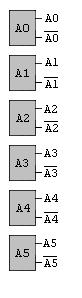
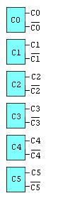
Similarly, we can depict the Drum Address Counter. For illustrative purposes, it is also shown as being 6 bits in length:
So how do we compare the 11-bit number in the Drum Address Counter with the 11-bit number in the Address Register?
Let us start with the traditional approach which uses logic gates. We compare A0 with C0 to see if they match (that is, both flip-flops hold a logic zero or both hold a logic one at the same time). We also compare A1 with C1 in the same manner to see if they match. We also compare A2 with C2 in the same way. This is repeated for each of the 11 bits and the 11 results are combined to see if all 11 matches are occurring at the same moment in time.
It is time to introduce the logic element called the Exclusive OR gate. Here is what one looks like in a logic diagram:
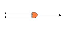
This logic element has two inputs. Stated simply, if the two inputs are different (that is, one input is a logic one and the other is a logic zero), the Exclusive OR gate outputs a logic one. If the inputs are the same, the Exclusive OR gate outputs a logic zero. I sometimes call them "Difference Detectors" because they output a logic one when the inputs are different.
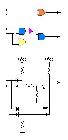
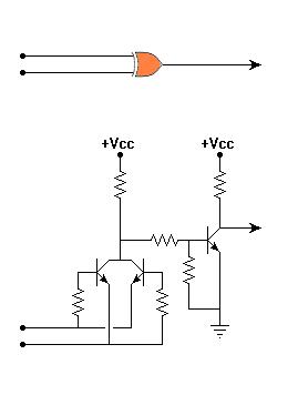
One way to construct an Exclusive OR gate is to make it from other logic elements. One such implementation consists of an OR gate, an inverter, and two AND gates. This diagram shows the Exclusive OR gate symbol at the top, then the equivalent to it as constructed from the other logic elements, and then the discrete component circuitry it takes to implement an Exclusive OR gate in this way:
Another way to construct an Exclusive OR gate is with a discrete component circuit that takes a somewhat more direct route as depicted here:
Given that we have one or two ways to build Exclusive OR gates, let us try to compare a bit from the Drum Address Counter with the corresponding bit from the Address Register. You would think that we would connect the Exclusive OR gate to the output of each of the two flip-flops involved in this way:
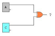
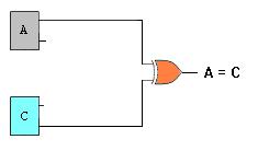
However, this does not get us what we want. We want to know when the two flip-flops are in the same state. Due to the way the Exclusive OR gate works, this circuit would output a logic one from the Exclusive OR gate when the two flip-flops are different from one another, not when they are the same as one another. The simplest way to correct this is to compare the top output of one of the flip-flops with the bottom output of the other flip-flop. The circuit then looks like this:
Given that this circuit successfully compares one bit of the Drum Address Counter with the corresponding bit of the Address Register, here is how we expand on this to get all 11 bits compared and combined into a single signal:
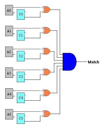
The AND gate combines the outputs of the 11 Exclusive OR gates to detect when all are indicating a match.
Now back to the story of constructing a home computer and trying to do it with a minimal number of parts, especially the more expensive ones such (at the time) as transistors.
Depending on which Exclusive OR gate design is selected, exclusive of the flip-flop circuits, implementing the approach described above requires either 33 transistors and 11 diodes or it requires 11 transistors and 66 diodes.
I finally arrived at a novel approach that would probably curl the lip of a few purists but it certainly did the job well and required far fewer parts at just 3 transistors and 24 diodes.
Most electronics enthusiasts already know about a simple voltage divider. It typically consists of 2 resistors joined in series. The point where they meet assumes a voltage somewhere between the voltage applied at either end of the circuit. In the circuit shown below, if the two resistors have equal resistances, the output voltage will be half way between Voltage 1 and Voltage 2.
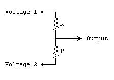
If the two voltages being applied are logic level signals (such as 0 volts and +5 volts), the output will be +2.5 volts. If both inputs are at 0 volts, the output will be 0 volts. If both inputs are at +5 volts, the output will be +5 volts.
Next comes a simple diode circuit, the Diode OR gate. Diodes are like little valves allowing current to flow in only one direction. Although technically, electricity consists of the flow of electrons and electrons have a negative charge, it is sometimes easier to think of electricity as consisting of the flow of the holes in solid structures where electrons are missing. This sounds like some kind of gibberish until we say it this way, "A positive charge flows through the arrows of diodes and transistors in the direction that they point."
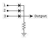
With regard to the Diode OR gate, the most positive charge coming into input 1, 2, or 3 will appear at the output. Actually, it will be diminished by the forward voltage drop of a diode (about 0.6 volts) but most of it will still be there. So when we use this as a logic OR gate, if there are any ones (+5 volts) present on any of the inputs, almost all of the +5 volts will be present at the output. That is, after all, exactly what an OR gate does. In any OR gate, the output is a logic one if any of the inputs is a logic one. The resistor assures that if no inputs are at a positive voltage, the the output will be pulled down toward ground which represents a logic zero. If you need such a gate with more inputs, you just add more diodes.
Now we look at the negative counterpart to the Diode OR gate, the Diode AND gate.
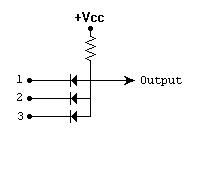
In this circuit, the most negative charge (also read as the least positive charge) coming into input 1, 2, or 3 will appear at the output. As before, there will be some loss caused by the forward voltage drop of a diode (about 0.6 volts). When we use this as a logic AND gate, if there are any zeros (0 volts) present on any of the inputs, 0 volts will essentially be present at the output. That is exactly what an AND gate does although we tend to say it the other way around. We say that the output will be logic one when all the inputs are logic one but that means the same thing. The resistor in the AND gate circuit assures that the output will be pulled up toward the +5 volt level unless one or more inputs prevent it by being at a more negative voltage than that. As before, if you need such a gate with more inputs, you just add more diodes.
Now we start to combine these toward the goal of detecting the matching condition. We now set up one voltage divider for each bit involved. In the real circuit, 11 bits required 11 such voltage dividers. Here we will show 6. Each of the voltage divider outputs is fed to both a large Diode OR gate and a large Diode AND gate.
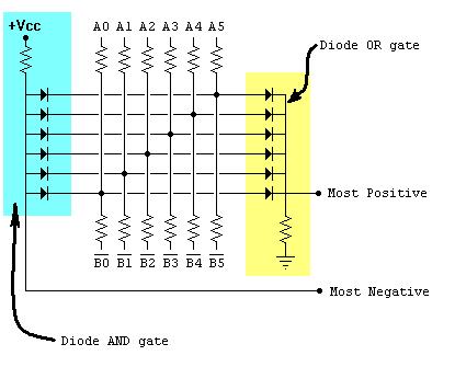
Let us consider what comes out of the two outputs of this circuit. If any given bit flip-flop of the Drum Address Counter and its corresponding bit flip-flop of the Address Register are in the same state, one of the inputs to the respective voltage divider will be at +5 volts and the other will be at 0 volts. The output from the voltage divider for that bit position will be at +2.5 volts. If there is not a match, either the output from the respective voltage divider will be 0 volts or +5 volts depending on which way they differ. Therefore, either 0 volts or +5 volts out means there is a mismatch.
Since we are doing this for all of the bits involved simultaneously, the output from the Diode OR gate is the most positive voltage coming from any of the voltage dividers. If all the bits are in a matching state, the Diode OR gate output will be about +2.5 volts, discounting the 0.6 volt drop from the diodes.
Meanwhile, the output from the Diode AND gate is the most negative voltage coming from any of the voltage dividers. If all the bits are in a matching state, the Diode AND gate output will also be about +2.5 volts, again discounting the 0.6 volt drop from the diodes.
If any bits are in a non-matching condition, either the Diode OR gate output will be more like +5 volts, or the Diode AND gate output will be more like 0 volts, or both. We just need a circuit to detect these conditions and combine the results into a single signal. Here it is:
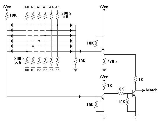
Just as you can see how this circuit showing the comparison of 6 bits can readily be expanded to compare 11 bits, so could it be expanded to cover many more bits.
UPDATE: Sometimes many years of experience give us new insights into old problems. Now that I have recalled and described the type of circuit that I used on this home computer more than 45 years ago, when I look at it again now, I see how to simplify it further. These resistor values might need a tiny bit of tweaking but I bet they would work as noted here:

In any case, this approach may prove useful to someone someday. I hope so.
To email me, send to:
![]()
