
The BOLT is a small simple computer used for learning and experimenting. Based on the 18F2550 integrated circuit of the popular PIC microcontroller series from Microchip Technology Inc., a company called Punto Flotante S.A. in Mexico has brought together several very important elements especially useful to electronics hobbyists. They sell the BOLT circuit board in two different versions which allows one to choose the type best suited to their own needs.

The full BOLT is shipped with several additional accessories, namely a 16-button keypad, a 16-character LCD display, and a USB cable as shown here:

The much simpler BOLT Lite version shown here uses the same printed circuit board but is minimally populated. That is, many of the board's components are omitted. It is shipped without the keypad, the display, or the USB cable.

Here, the major components of a full BOLT board have been identified:

Even the minimal BOLT Lite board includes enough elements to enable learning about microcontrollers as well as providing a basis for conducting many experiments and developments. Here are the most important parts of the BOLT Lite board that permit such use:
These last three parts of the system permit you to install new programs of your own design into the BOLT and try them out.
I am an electronics experimenter and I enjoy tinkering with microcontroller systems. I personally liked the idea of these simple BOLT computers and starte with two of the BOLT Lite boards. Later, I added a full BOLT system. A friend of mine who lives 2,000 miles away found out about them and began acquiring some BOLTs of his own. We regularly exchange ideas, software, and parts.
Armed with only the basic elements in a BOLT Lite, I set out to learn about the PIC 18F2550 and and to display information on an LCD display.
Like probably everybody else, my very first efforts involved loading and running a very simple LED blinking program. I worked my way up from there.
Retired now, for more than forty years I wrote computer programs for a living. I was professionally writing software more than a decade before the C computer language was even created. I have written many programs in assembly language (some call it assembler but I prefer assembly) as well as many high level languages.
When others around me heard about C, they were sure that I would quickly take to it like a duck takes to water. Sorry to say, that just never happened. To this day, I just do not like the odd syntax conventions of the C language. Unfortunately (for me), for some reason, most of the world has settled on using C for programming microcontrollers. There are a few implementations of BASIC that will run on microcontrollers but none of the free ones have caught my fancy so far. I am too cheap to spend much of anything on a compiler. Besides, you can get the most out of a processor if you take the time to write your programs in assembly language. So that is where I am now. I write my BOLT programs in PIC 18F2550 assembly language.
Punto Flotante S.A. provides some example programs for the BOLT system written in C and a few in assembly language. I had some previous experience with other smaller PIC series processors and the assembly language that they use. I had developed in the past some macro definitions for assembly language programming that made it a bit more readable and made it look a bit more like the assembly language commands associated with other computers and minicomputers from my past. So I read the example programs and then started developing some of my own assembly language routines for the BOLT system.
Right after the LED blinking experiment is when I decided to start writing routines to support LCD character displays that I had on hand even though I had never programmed one before. That made for an additional hurdle in the mix.
Such LCD character displays are the fairly common type that use the Hitachi HD44780 LCD controller chip or equivalent. When I began, I still had not acquired the full BOLT system and had only a BOLT Lite board. I knew that the full BOLT utilized an LCD display of 16 characters all on a single display line.
I found out the hard way that many websites that seem to present "the way" to program these displays do not always agree with one another and what they say to do sometimes does not work at all or not for all the different types of such displays.
I have routines working now that I believe will work for all of the displays except those with more than 80 characters displayed. For example, it will not work with a 40 character by 4 line display because such displays use two of the controller chips instead of one.
It turns out that some LCD character displays have use a somewhat unexpected organization to save costs. That presented a couple of programming challenges at first. The 16 character by 1 line display shipped with the full BOLT is of this type.
One of my missions while working with the BOLT boards has been to find ways to make them more useful, both in extending the types of peripherals that may be connected and in devising ways to connect more peripherals at one time. I am not yet finished in moving that direction but I am on my way. On this website, you will find information describing my activities, and those of a distant friend, along these lines.
Here are a few additional facts about the BOLT boards:
Punto Flotante S.A. apparently uses eBay as a major outlet for selling their products. Look for a seller ID of "edukey100".
There were times in the past when the seller offered some BOLT boards in auction format and others in the "Buy It Now" format. In more recent times, they seem to appear only in the "Buy It Now" format but the prices have dropped somewhat from their original levels. Typically coupled with "Free Shipping", they really are a pretty good deal in my estimation. Besides looking for these products by looking for the seller's ID, you can try searching on eBay for the following:
Bolt 18F2550 PIC USB Microcontroller
The BOLT boards are offered in two versions:
In moving on to the LCD display, the first step had to be getting an LCD display module plugged into the BOLT. The artwork for the LCD connector is a row of 14 holes across the front edge of the board. However, the LCD displays that I had at the time had 16-pin connectors. A little research showed that the extra two pins (pins 15 and 16) are used to power a backlight in many LCD displays. It is even very common for LCD displays that have no backlight feature to have all 16 pins with the last two pins just connected to nothing. These photos show the 14 LCD connector pads on the BOLT Lite, an LCD display module with a 14-pin connector, and an LCD display module with a 16-pin connector (the type with which I started out):


The type of display shipped with a full BOLT system has a plug with only 14 pins. In fact, it is the LCD display from a full BOLT system that is pictured above as the 14-pin example.
Here is my solution to the issue. I installed a 16-pin female header in a laying down orientation by bending the first 14 pins downward 90 degrees and leaving the last two pins (15 and 16) straight. In fact, I bent them up slightly to improve my ability to solder to them.

Now let us discuss what should be done with those two extra pins. Pin 16 should be connected to ground. Pin 15 should be connected to a source of power for the backlight. Many (but not all) LCD displays have a built-in current limiting resistor in the backlight LED circuit. For these, one could connect +5 volts directly to pin 15 but that might not be the wise thing to do. Instead, I opted to install a 150 ohm resistor between a source of +5 volts and pin 15. This serves as a current limiting resistor if there is none on the LCD module. It still allows sufficient current to pass even if the LCD module does have its own current limiting resistor.
Here is where a source of +5 volts and ground can be found on the BOLT board for connection to these two pins:


Here are some photos of the current limit resistor and ground wire being added. Afterward, I secured them in place with hot melt glue.


Even if you use a 14-pin LCD display for the time being, providing the two extra pins will lay the groundwork for the day when you want to use a 16-pin display module.
The full BOLT board does not come with a 16-pin LCD display connector. It comes with a 14-pin connector. If you have one of these, the connector can be extended by gluing a 2-pin female header to the board at the end and then adding the ground wire and current limiting resistor as described above.
Some LCD display modules have a facility for backlighting that does not employ one or more LEDs to generate the light. Often, this takes the form of an electroluminescent panel. The electroluminescent panels require special circuitry to generate their necessary higher voltages to make them glow. The same pins (15 and 16) are usually used for powering these backlight panels. If you have an LCD display module that employs an electroluminescent panel for backlighting, it will not damage it to be plugged into the +5 volts and ground on pins 15 and 16 but neither will it glow or will glow very little. Still such LCD display modules are usually usable with the BOLT but will depend on ambient light to be seen.
If you add a connector to a BOLT Lite board so that you can plug in an LCD display module, there is one other step that is needed before it will operate properly. Pin 3 of that connector needs to provide an analog signal to the LCD display that indicates the LCD's contrast level. On a full BOLT, this contrast level is generated by a simple circuit consisting of two resistors, namely R18 (1K ohms) and R19 (100K ohms). Together they form a voltage divider that produces a very small positive voltage of about +0.05 volts for the LCD contrast signal. This particular voltage may be pretty good for the 16 character by 1 line display that is shipped with the full BOLT systems but is not always appropriate for other types of LCD modules.
Every other LCD display interface circuit I could find on the internet indicated the use of a pot (potentiometer) to generate the LCD contrast signal. Typically, a 10K pot is used but other values ranging from about 3K or so to perhaps 25K will work fine in this application. When I decided to add the LCD connector to my BOLT Lite boards, I also installed a 10K pot on each board instead of R18 and R19. These photos show how I did it:


What is important is that one end of the pot be connected to ground. The other end should be connected to +5 volts. The wiper (usually the middle pin) then becomes the adjustable contrast signal and should be connected to Pin 3 of the LCD connector.
If you have a full BOLT board, it already has the R18 and R19 resistors. You might be asking what to do if you want to incorporate the adjustable LCD contrast control on the full BOLT. You have two choices. The first choice is to disconnect or remove the R18 and R19 resistors and then install the pot as described above. The second choice is to just leave R18 and R19 in place and then add the pot as shown before. However, if you choose this option, it will work best if a relatively low value of pot resistance is used such as 3K ohm or so.
The BOLT board was designed to use a DS18B20 temperature sensor in the location on the board marked as U4. This sensor is a 3-pin device. As you can see in this photo, U4 shows the symbol one typically sees used for a transistor and, in fact, this sensor does look just like a transistor. The three holes in the board are arranged 0.1 inches apart and in a straight line. The spacing makes this little area suitable for installing a 3-pin female header as shown in these before and after photos:

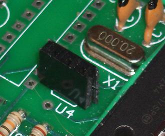
The hole that is farthest from the processor chip is connected to ground. The hole closest to the processor chip is connected to +5 volts. The hole in the middle is connected to pin 5 of the processor chip as well as a 10K ohm pullup resistor that tries to pull this signal high. When used for sensing temperature, pin 5 of the processor would be placed in its analog input mode by the software and would be identified as analog input 3. However, if the software sets the pin's mode to be a digital input or digital output, this little 3-pin connector becomes a handy place to connect some experimental digital circuitry, complete with ground and +5 volt power.
In my own experiments, I have often plugged an LED with a current limiting resistor into this little socket to serve as an extra indicator while testing software routines under development.
By the way, in the full BOLT system, the DS18B20 temperature sensor device is not soldered into the board here but is actually plugged into a 3-pin socket that is basically a bit higher quality version of a 3-pin male header. Here is what it looks like, with and without the temperature sensor in place:


The BOLT is designed to drive an on-board relay (labelled RL1 on the board). The relay presents normally open (N.O.) contacts to the external world using a 2-screw terminal block (labelled J4 on the board). If you have a BOLT Lite, your board does not include this relay, its driver circuit, or its associated LED. Here you have several options, the least of which is to make use of the Input/Output pin normally reserved for running the relay and its LED.
If you just want to get hold of this I/O line for your own purposes, one place to access it is one of the circuit board holes for resistor R7, namely the one at the end of the resistor closer to the processor chip. Used in this way, the I/O line can serve as an analog input line (AN0) or a digital input or digital output line (RA0).

Another option is to install driver transistor Q1 (BC337), resistor R7 (5.6K ohms), LED D2 (any color you wish), and resistor R6 (1K ohms). This would allow the LED to be driven by the digital output RA0, even though the relay is not installed. By the way, a 2N2222 transistor can be substituted for the BC337 as Q1. However, if doing this, turn the transistor directly opposite of the way the transistor image shape is printed on the circuit board. That is, the flat side of a 2N2222 should be toward the processor.
Yet another option is to install all these same components plus relay RL1 and diode D1 (1N4148) as well as the components needed to supply power via an external power supply such as an AC adapter. I found that the relay used on the full BOLT board (SUN HOLD RAS-0910) is difficult to locate. Then I discovered that Radio Shack sells a relay that serves as a very good substitute for the SUN HOLD model. The Radio Shack item number is 275-0005. The Radio Shack relay has a suitable coil resistance (500 ohms), is blue, is the same size, and has the same pin-out as the SUN HOLD version. Its contacts are rated higher than those of the SUN HOLD model.
The reason the external AC adapter circuitry must be installed in order to use the relay is that the relay is not powered by the +5 volt power supply. Instead it is powered directly by the 9-volt DC power supply. This is true even if the BOLT is being powered by the USB cable. If you wish to power the relay but do not wish to generate +5 volt power for the other BOLT circuitry from an external 9VDC AC adapter, the additional components that need to be installed include:
Technically, the relay might work even without the capacitor installed but it might be a little buzzy depending on the type of AC adapter used. NOTE that there is more to know about this capacitor that is described later. Check that out before you solder one in.
On a BOLT Lite board, you can see that there is a space reserved for an entire integrated circuit that is not present, namely U3. This is intended to be a MAX232 chip. The purpose of the MAX232 chip is to adjust the voltage levels of the serial input and serial output signals. RS-232 serial signals typically operate somewhere in the vicinity of +/- 12 volts whereas the logic signals into and out of the processor chip are +5 volts and 0 volts. The MAX232 chip performs this voltage conversion in both directions for us when we want a serial port that meets the RS-232 standard.
These days, we often see devices communicating serial data using the voltage levels normally associated with logic circuits (+5 volts or so for a "1", 0 volts for a "0"). This is sometimes referred to as TTL serial because the +5 volt/0 volt convention came into existence pretty much at the same time as Transistor-Transistor Logic (TTL) about 50 years ago. If you would like to use the serial transmit and receive lines for TTL serial communication instead of RS-232 communication, you can access the signals at the printed circuit artwork for U3. The TTL serial transmit signal is available at pin 10 and TTL serial receive is at pin 9. Also, +5 volts is available at pin 16, and ground is available at pin 15.
If you do not wish to use these two signals for transmitting and/or receiving serial data, each one may be assigned a role as a digital input or digital output line. The signal at pin 10 of the U3 socket corresponds to digital I/O pin RC6. The signal at pin 9 corresponds to digital I/O pin RC7.

One would think that installing two 8-pin female headers in the U3 artwork would permit plugging in a MAX232 chip to permit using the RS-232 serial port. Then removing the MAX232 would permit easy access to the signals for use as TTL serial or digital I/O. However, a female header usually does not work well as an IC socket. Perhaps soldering two 8-pin male headers to the pins of a MAX232 chip would work into two 8-pin female headers on the board but it would surely look peculiar.
NOTE that if the MAX232 is to be used, the four capacitors (C3, C4, C5, and C6) must all be installed in order for it to operate. Installing these capacitors has no effect on using the signals on pins 9 or 10 or the use of +5 volts at pin 16 or ground at pin 15. All four of these capacitors should use the same value, 10 ufd with a voltage rating in excess of 25 volts.
If you have a full BOLT board but would rather use the TTL serial transmit and receive signals or you would rather take advantage of the two digital input/output signals, RC6 and RC7, you can just carefully remove the MAX232 chip from its socket and access the signals at the same pin locations as shown above.
There is another place where an additional digital input/output pin can be found. It is hiding in the Bootloader jumper circuit associated with JP2. First, let us review a bit about the use of this jumper. JP2 has three pins as shown here:

The jumper block can be plugged onto these pins in either of two positions. When we want the BOLT system to run an application program that has previously been stored into its Flash memory, we put the jumper into its "Run" position which is more to the left as shown here:

NOTE that it would appear that the JP2 jumper is incorrectly labelled as the word BOOT printed on the board seems to be on the wrong end of JP2.
When we want the BOLT system to contact the PC via the USB cable and to accept a new program into the Flash memory for us to run in the future, we put the jumper into its "Bootloader" position which is more to the right as shown here:

When I started writing programs for the BOLT system, I found that I was moving this jumper back and forth between these two positions every couple of minutes as I made one program version after another for testing. That got old pretty fast so I decided to see if I could not substitute a switch for the jumper.
The truth is that the BOLT system only checks the position of this jumper (or switch) immediately after the processor experiences a reset. This happens when power is first applied or when someone presses and then releases the Reset pushbutton on the BOLT board. After examining the circuitry associated with the JP2 jumper, I could see that a simple momentary switch could be used that was only connected to the two pins to the left. Unfortunately, the switch had to be of the normally closed variety that momentarily opens the circuit when its button is pushed. In other words, it is like a refrigerator door switch that turns the light on when the door is opened. Pushing the button in breaks the circuit. Allowing the button to pop out closes the circuit.
It took me a while but I found one. I call this pushbutton switch my Bootloader button. Here is what it looks like when plugged onto JP2:

The procedure then became this: I could tap the Reset button and the current application program in the BOLT would start running. To cause the Bootloader to run so the BOLT would contact the PC and allow the downloading of a new program for testing, I would press and hold the Bootloader button while I tapped the Reset button. As soon as I removed my finger from the Reset button, I no longer had to hold the Bootloader button because by then the BOLT had decided which function it is to perform, either to run the existing application or start the Bootloader program.
I continued in this way for quite a while but I kept wondering how most people would find a momentary action normally closed pushbutton switch like mine. They are not very common. I studied the JP2 circuitry some more. The signal from this jumper feeds into the RC2 pin (pin 13) of the processor chip. This pin which could be capable of being a digital input or output signal is being consumed for a purpose that lasts only a few microseconds following each Reset cycle.
I worked out an alternate version of the circuitry associated with JP2.
In this schematic we can see the original JP2 circuit of the BOLT. It is shown here twice, once with the jumper in the "Run" position and once with the jumper in the "Bootloader" position.

When the jumper is in the "Run" position, a low signal is generated into the RC2 pin of the processor. When the jumper is in the "Bootloader" position, the 10K ohm resistor pulls up on the signal line, generating a high signal into the RC2 pin of the processor. At those times when an extra input or output pin could find some use (that is, when an application program is running) the RC2 line is solidly grounded by the jumper in its "Run" position.
When my "Bootloader" button is connected to the original circuit, it is plugged onto the lower two pins of JP2 in this schematic. Remember that it provides a closed circuit when running an application and opens the circuit to start the Bootloader.
This revised version of the JP2 circuitry is also shown twice, with its jumper in both the "Run" and "Bootloader" positions. First, note that the jumper is in the same physical positions as before, the lower two pins of JP2 for "Run" and the upper two pins for "Bootloader". The additional cost is minimal, requiring only one extra resistor. On first glance, it is not evident why the extra resistor (the 270 ohm resistor) is even required. Why not just replace it with a piece of wire? We will discuss that in a moment.

How does this affect the idea of plugging a Bootloader button onto the JP2 jumper pins similar to my original Bootloader button?

In this circuit, the switch goes on the upper two pins of JP2 and is of the much more common normally open type of switch. When not pressed, it appears as an open circuit and the 10K ohm resistor provides a low signal to RC2. This is the "Run" condition. When the Bootloader button is pressed, it provides a conductive path via the 270 ohm resistor that pulls the RC2 signal high which is the Bootloader condition. Furthermore, if nothing is plugged onto the JP2 jumper at all (that is, no jumper or Bootloader button is present), the BOLT system will always come up running the application program in its Flash memory. Here is my new Bootloader button plugged onto JP2:

By using a normally open pushbutton instead of a jumper, we have effectively added an additional digital input or output line. The RC2 signal is available on the middle pin of the JP2 jumper. Suppose you connect it to some circuit or device that you wish to drive, using it as an output signal. When the BOLT system comes up, the RC2 pin will still be pulled low by the 10K ohm resistor. When the application program starts, it can mode the RC2 pin as an output and then begin driving it high or low. Whatever circuit you have connected to that line will now be controlled by the application program.
The only drawback will be that if you momentarily hold RC2 high while you press Reset in order to enter the Bootloader, whatever you have interfaced to the RC2 signal will be turned on momentarily by the brief high signal on RC2. In many cases, this would not matter. It is also important that whatever output circuitry is added does not cause the RC2 line to be pulled high as this would cause inadvertent start up of the Bootloader upon a reset cycle. Still, this is not much of a limitation.
Next, let us consider using RC2 as an input signal. If the application program modes RC2 as an input, it can easily read the state of that line. Since the new momentary contact pushbutton is already connected to the RC2 input, once an application program is started, the application program can simply read the state of the RC2 input. Therefore, as soon as the application program starts, a human can press and release the button (that I call the Bootloader button) and the application program can respond to the associated changes in the state of RC2.
Of course, the input signal could come from some device other than the pushbutton. The only drawback to this operation is that you would not want the input circuitry that you add to cause RC2 to be pulled high during a Reset operation because that would trigger a start up of the Bootloader.
It is is even possible for this to be used as both an input and an output in the same application. Here is a simple circuit that does the job:

When the application program starts, it could mode RC2 as a digital output and begin driving the LED or not as the application program sees fit. While it is doing that, it could keep repeating a simple operation to see if the pushbutton is being pressed. Perhaps every 50 milliseconds or so, it could change the mode of RC2 to an input, check the state of it as an input, and then return it to being an output and set it according to whether it wants the LED on or off. Since the entire input sampling operation could be conducted in a few microseconds, the temporary interruption in the output to the LED would never be seen by the human eye except that the LED would be on while the button is being held down. If the function of the button is to toggle the state of the LED in the application program's software, the result would be very natural looking, indeed.
Here is how to modify a BOLT board to use the revised JP2 circuit:


Although there was already a 10K ohm resistor involved in this circuit, it proved most easy to just leave it disconnected and add a new 10K ohm resistor as well as a new 270 ohm resistor. Only one land needed to be cut and then the two resistors soldered in place.
Now back to a question eluded to earlier. Why is the 270 ohm resistor required? Imagine for the moment that there was no 270 ohm resistor there. Suppose it is simply replaced by a piece of wire. Now suppose an application program is running that has moded the RC2 pin as an output and is currently driving that line to ground. Now suppose you decide to start the Bootloader. You press a button or install a jumper that ties the top two pins of JP2 together in preparation for pressing Reset to run the Bootloader. At that moment, the processor is trying to drive RC2 to ground and the jumper has it tied directly to +5 volts. That is absolutely a bad idea for the processor chip. So the purpose of the 270 ohm resistor is to act as a current limiter in this particular case. It protects the processor chip from being fried.
If the configuration is set up properly, the PIC can be used without the /MCLR reset signal. If this is done, the PIC processor will reset itself upon power up. The signal from the Reset button will simply appear to the application program as input RE3.
If your application does not make use of the USB port, the RC4 and RC5 signals become available and are accessible at the USB connector along with ground. While RC4 and RC5 cannot be used as digital output signals, they can be used as digital inputs if the configuration registers are set up properly. Like RC4 and RC5, RE3 as described above can only serve as an input line, not an output.
If you wish to have RC4 and RC5 act as digital inputs, you will also need ground in the related circuitry. All three signals can be found at the USB connector of the BOLT board. While it would be possible to also bring +5 volts to the USB connector by powering the BOLT with an external supply and then connecting all three pins together at JP1, this procedure is not recommended since the odds are great that a USB cable might be plugged into the USB connector and a PC at the same time resulting in an undesirable situation concerning power in the USB interface.
When I set out to add a connector to a BOLT Lite board for J7, I was aware that the full BOLT normally uses a male connector there. However, I prefer a female connector for that location because it lets me plug wires or components into the port more easily for experimentation. So I chose to use a female header connector laying on its side. I knew that if I wanted to connect a BOLT style keypad I could easily fashion a male-to-male adapter to plug into the BOLT board and into the keypad board.
As I was about to get a female connector together for J7, I realized that the 8 pins of the connector include only 8 digital input/output signals. Ground does not appear anywhere on this connector. So I looked at adding another pin or two to the connector. I managed to fit two more pins onto the end of this connector. It is unfortunate that they are on the pin number 1 end. I suppose my extra pins are pins 0 and -1. In any case, I put ground on pin -1 but wondered what would be best on pin 0. I gave consideration to putting +5 volts there but +5 volts is available very nearby on pin 6 of J6. So I decided to wire pin 0 of J7 to the Reset signal because that was available externally no where at all. Momentarily grounding that pin can reset the BOLT via an external circuit. Also, an external circuit can be reset by the BOLT's Reset button at the same time the BOLT system is reset using this signal.
One thing observed about J6 and J7 is that while they are directly in line with one another, the distance between pin 6 of J6 and pin 1 of J7 is not a multiple of 0.1 inches. This prevents a single male or female header from being used across both connectors. There is a similar loss of alignment between the pins of J7 and J5. Perhaps a future version of the BOLT board could have these alignments modified, permitting one long connector to be used for J6 and J7 or all three J5, J6, and J7 being able to easily align with a piece of standard prototyping board. I would bet that some experimenters would welcome that change.
If using vertically oriented female headers for all three (J5, J6, and J7), the BOLT would begin to somewhat resemble an Arduino. BOLT shields could then be created that stack on top of the BOLT. Such shields could include LCD displays and keypads as well as all the other motor controllers, network interfaces, sound systems, video generators, and all the rest.
The BOLT board uses jumper JP1 to determine the source of +5 volts which powers the PIC processor chip, the MAX232 chip (if it is present), and the LCD display module (if it is present). In the position marked USB, the jumper selects the USB cable as a source of +5 volt power. In the other position (which is not marked) jumper JP1 selects the 7805 regulator circuit as its source of +5 volt power (if the 7805 regulator is present). Even when present, the 7805 can only supply +5 volts if an appropriate AC adapter is plugged into receptacle J1. As shipped, the BOLT Lite does not include the 7805 regulator but you can add one yourself.
By the way, the relay is not powered by +5 volts (although the relay LED is). The relay is only powered if an external power source such as an AC adapter is plugged into J1. The 7805 is not needed in order for the relay to receive its power at times when JP1 is set to the USB position.
If your BOLT is set up to use power from an external source (other than USB) you can run an application program that has been stored into its Flash memory without your PC being involved.
There are several possibilities for providing external power to the BOLT. In order to do any of these, you will either need a full BOLT board or a BOLT Lite that has had several components added. At the least, these components would include C12 (10 uF electrolytic capacitor, 16 Volt or higher), C2 (10 uF electrolytic capacitor, 16 Volt or higher), C1 (100 nF), 7805 3-pin regulator, and receptacle J1 to accept the AC adapter plug. You will also need an AC adapter that outputs 9 VDC. The recommended AC adapter is rated for 300 milliamps. The center conductor of the adapter plug must be positive. To be certain about this, your AC adapter should have this symbol printed on it to indicate that positive is on the center terminal:

Suppose you started with a BOLT Lite board and cannot find a receptacle that fits those J1 holes in the BOLT circuit board or suppose you can find such a receptacle but it would do no good to solder it to the board because your AC adapter does not fit that particular receptacle anyway. Here are a few alternatives. The objective is to get a source of +9 volts DC relative to ground to the two appropriate pins:

Regardless of the kind of connector that is on your AC adapter, get the more positive lead connected to the pad marked +9 VDC in the photo and the more negative lead connected to the pad marked Ground. You can solder wires from a connector to the board so you can plug your AC adapter into the connector or even just remove the plug from the end of the AC adapter wire and solder the two wires to the J1 pads directly.
NOTE that you must be careful here. Applying power to the BOLT board with the polarity reversed is likely to do serious damage. Luckily, there is a thing or two you can do to protect yourself against that happening.
Here is the schematic for the BOLT external power supply circuit:

There is a modification that you can make that prevents damage in the event that external power is applied in the reverse polarity. A diode is like a one-way valve. Electricity can only flow through it in one direction. Adding a diode in the correct place in the circuit can not only prevent such damage, it can also allow us to use an AC adapter that outputs AC instead of DC. However, when AC is processed through the diode, the resulting DC is about 40% higher than the AC that fed it. The diode itself drops about 0.6 volts in the process. To arrive at +9 volts DC, we should start with about 7 volts AC.
(7 VAC x 1.40) - 0.6 VDC = 9.2 VDC
8 volts AC would also work acceptably. If you do not have a relay installed, somewhat higher voltage would cause no real problem for either AC or DC type adapters. If you notice the 7805 regulator getting pretty warm, you should think about getting an adapter with a lower voltage output.
Another source of external power could be a set of batteries. You get 9 volts DC when you connect 6 batteries in series. (Each battery contributes 1.5 volts.) Batteries that would work well for this would include AAA, AA, C, and D types. Using larger batteries means the BOLT would run longer before the batteries were exhausted. A set of 6 D batteries would last much, much longer than a set of 6 AAA batteries. Of course, 6 D batteries would be much larger and weigh more, too. Of course, alkaline batteries last longer than standard carbon types.
If you are wondering if you could run the BOLT in an automobile, that can be done also, especially if you do not have a relay on the board. The coil of the relay is rated for 9 volts DC and it is fed from the DC supply just as it comes in to receptacle J1. (If you add the diode described below, the relay gets the power after it goes through the diode.) So the relay is the main reason for being concerned about the incoming power being not much greater than 9 volts.
I once wanted to take a BOLT with an LCD display module to a small meeting to show some friends. I tried connecting a single 9 volt battery as a power source. It did work but the battery was pretty far gone even before this. So the BOLT soon began to fail to operate correctly. To remedy this, I just snapped a second weak 9 volt battery onto one of the first battery's terminals, placing them in series. Was the total actually 18 volts? Probably not but it ran the BOLT and display just fine. The BOLT had no relay.
If you are thinking of using an adapter that produces AC, it would be smart to increase the capacitance of C12 from 10 uF to something like 100 uF or even more. On one of my BOLT boards, I used a 1000 uF capacitor. An increased capacitance value for C12 would not preclude the use of an adapter that produced DC. Here is a schematic diagram for the revised external power supply circuit:

This schematic shows a 1N4001 diode being used but any diode from the series 1N4001 - 1N4007 will work fine.
And here is how to add the diode:


When I started to use my first BOLT, I found myself plugging the USB cable into the BOLT and removing it very frequently as I swapped my LCD display modules around a lot during LCD software debugging. I could have been pulling and replacing the jumper JP1 to cut the power during the LCD swaps but pulling and replacing the USB cable was much quicker and more convenient. At one point, I suddenly found that my BOLT would no longer contact the PC so that I could download a new program for testing. By the way, the BOLT was still able to run the last application program that I had stored into it but I could no longer change it with the Bootloader because the USB interface capability was gone.
I contacted Punto Flotante S.A. and arranged to buy a replacement 18F2550 chip. Still I began to investigate what might have gone wrong. I found that the metal shell of the USB receptacle J2 is not grounded on the BOLT. I thought that this must be an oversight so I began to investigate on line as to what the USB standards might say about that. I found that there seems to be a wide difference of opinion as to what degree and how the shell should be grounded. My thinking is this: My ohmeter shows that the metal shield on the end of my USB cable is connected to my PC's ground when the cable is connected to the PC. At the risk of inflicting my system with a ground loop, I decided to ground the metal body of the USB connector at the BOLT end as well. I suspect what damaged my processor chip was that handling the BOLT or moving things around on my work table may have put some level of static charge into the BOLT. Then the next time I plugged the USB cable into the BOLT, the first conductor that made contact was one of the USB data lines. That could have zapped that line. By grounding the metal body of the USB receptacle, I cause the ground circuit of the BOLT to make contact with the ground of the PC before either of the USB data lines makes contact, thereby harmlessly discharging any such static charge.
I just used a piece of wire to add the ground. Some might suggest the use of a resistor instead, maybe something like 100 ohms. In any case, here is how I added the ground to my BOLT boards:

Anyone knows that plugging in and removing the USB cable to control power is not the most stylish way to do it anyway. I decided I needed a power switch. A somewhat better version could be fabricated but I went with a simple version. I soldered a miniature SPDT (single pole double throw) slide switch to a 3-pin female header and plugged it onto the JP1 power select jumper pins. Flipping the switch is the same as moving the power select jumper. As long as only one source of power (USB versus external power supply) is available, the switch serves as an On/Off switch. If both sources are available, the switch serves as a power source select switch. The photos tell the tale:


HOME
To email me, send to:
![]()
