The front suspension uses a piece cut from the center of a downhill ski. I am hoping to find one that is all fiberglass; but, for now I am using a fiberglass reinforced wood one that I picked up at a thrift store for $2.
Note the aluminum support for the front of the seat. The tubes for the seat extend past the steering drag links and I weigh enough that the front of the seat sagged down and would hit them on bumps (not good). You can see this clearer in a photo further down the page.
For the rest of this page I will describe how I constructed the steering knuckles and spindles.
|
 |
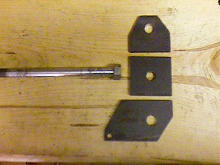 |
I made the steering knuckle out of 1/4" x 2" mild steel. Probably overkill, but I figure better safe than sorry. Here are the pieces before they are welded together. The center piece has the axle welded to it and then the other pieces are welded on. To keep the pieces aligned properly I used a piece of wood. I clamped the top and bottom to the wood (after making sure the surfaces were parralel) and then clamped the middle piece to the end.
Sorry I didn't think to take a picture of the assembly jig. |
| You can see here that part of the bottom piece sticks out and has a hole drilled in it. This was where the drag links were going to attach, but it wasn't far enough out to clear the support. |
 |
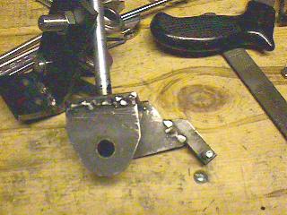 |
I fixed this by welding on an extra piece to reach out a bit further. You can also see how I rounded off the corners with a grinder. I didn't do this before welding because I wanted straight square sides for the clamps. Grinding the corners off wasn't neccesary, but it lightens it up a little bit and looks better. |
| Here is a closer look at the bottom. Notice the extra piece of metal welded on close to the axle. This piece engages a slot in the backing plate for the drum brakes and stops it from rotating when the brakes are applied. |
 |
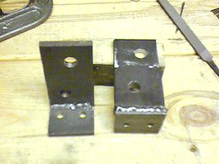 |
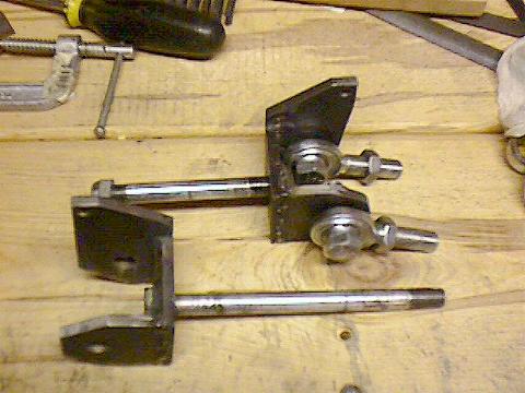
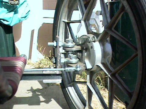
Here are the kingpin mounts. These bolt to the front beam (downhill ski) and the Heim joints bolt to them. If you look carefully at the one on the right you can see that the bottom half is actually two layers thick (see below for a clearer photo).
The Heim joints attach to the steering knuck in a stagered fashion to give the angle needed for centerpoint steering (A line drawn through the center of the heim joints should hit the ground inline with the center of the tire). The extra thickness on the lower part of the mount helps support the lower heim joint since it sticks out further.
Notice how the lower hole is not directly below the upper hole. The lower hole is further forward to provide approximately 11-12° of caster. |
| This is the completed assembly. You can see the extra layer on the mount a little clearer here. You can also see how the heim joints are staggered . |
 |
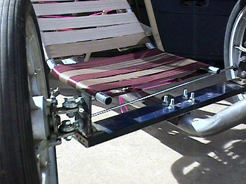 |
A different view of the completed assembly. Notice over on the right side how the seat hangs out past the drag links. This is what I was talking about at the top of the page. |
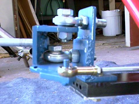
| Here is a close up of the assembly after painting. It's a bit fuzzy (too close with a fixed focus camera). However you can see everything that I was describing. |
 |

