
Abel Programming Basics
What ABEL programming can do:
ABEL is a programming software capable of providing a standard JEDEC file to the PLD devices.
ABEL programming Basics:
ABEL Number System:
^hA0 ^h means hexadecimal
^d10 ^d means decimal
^b1010 ^b means binary
ABEL Logic Operators
! - (NOT) invert function
# - OR function
& - AND FunctionWriting Boolean Expressions
Using ABEL Logic Operators, the above circuit can be written as;Y = !(A & B) # C & !D
Example:
Design an 4 channel Multiplexer circuit with inputs A to D and an output Y, select lines are S1, S0.
equations
Y = (A & !S1 & !S0 ) # (B & !S1 & S0) # (C & S1 & !S0) # (D & S1 & S0)
NOTE:The compiler directive "equation" is supposed to be placed before writing the boolean equation.
Using Truth Tables:A combinational circuit can be represented by a truth table. Truth table can be used in circuits where writing of un-simplified long equations will consume much time. ABEL software allows programmers to enter truth tables as a definition on how the logic circuit is supposed to operate. During the compilation process, the software itself applies simplification techniques to simplify the output boolean expression.
Example: Design a combinational circuit which will perform an Excess-3 operation. The input has 3 input lines (a,b,c) and 3 output lines (x,y,z).
The TRUTH Table:
Input Output
a b c x y z
0 0 0 0 1 1
0 0 1 1 0 0
0 1 0 1 0 1
0 1 1 1 1 0
1 0 0 1 1 1
1 0 1 0 0 0
1 1 0 0 0 1
1 1 1 0 1 0
Truth Table in ABEL programming;
truth_table ([ a, b, c ] -> [ x, y, z ])
[ 0, 0, 0 ] -> [ 0, 1, 1 ];
[ 0, 0, 0 ] -> [ 0, 1, 1 ];
[ 0, 0, 0 ] -> [ 0, 1, 1 ];
[ 0, 0, 0 ] -> [ 0, 1, 1 ];
[ 0, 0, 0 ] -> [ 0, 1, 1 ];
[ 0, 0, 0 ] -> [ 0, 1, 1 ];
[ 0, 0, 0 ] -> [ 0, 1, 1 ];
[ 0, 0, 0 ] -> [ 0, 1, 1 ];Sets can also play an important role in ABEL variables.
If the input can be assigned to a variable INPUT, we can assign variables a,b,c to it by using brackets "[ ]"
INPUT = [a, b, c];
The same can be applied to the output
OUTPUT = [x, y, z];
Re-writting the above ABEL truth table. . .
INPUT = [a, b, c]; " INPUT is a variable with a,b,c as members
OUTPUT = [x, y, z]; " OUTPUT is a variable with x,y,z as members
truth_table ([ INPUT ] -> [ OUTPUT ])
[ 0 ] -> [ 3 ];
[ 1 ] -> [ 4 ];
[ 2 ] -> [ 5 ];
[ 3 ] -> [ 6 ];
[ 4 ] -> [ 7 ];
[ 5 ] -> [ 0 ];
[ 6 ] -> [ 1 ];
[ 7 ] -> [ 2 ];
Since INPUT and OUTPUT are variables which has set of variables a,b,c and x,y,z respectively, what ever values assigned to the variables will be distributed accordingly to every member of the set.
A Design Exercise:
This is an example application where in I
applied the concept of PLD programming in an application.
The circuit to be designed was a Pulse Transformer Board which will be used to
trigger SCRs into conduction. The application was supposed to control a 3-phase line
voltage. Each phase to be controlled needs two(2) SCRs. As a result, six(6)
pulse transformer is needed.
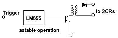
The OLD design approach was using six(6) LM555 timers as clock generator to
drive the six(6) darlington pair transistor which will eventually drive the six(6) pulse
transformers. The microcontroller needs six(6) available output lines for controlling the
board.
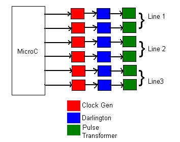
The PLD approach;
As seen from the diagram above, there are redundancy with the clock generators,
excessive I/O line usage.
The Clock Generator Circuit:
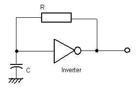
This is a classical clock generator circuit application using an inverter, a
capacitor, and a resistor.
The Overall Block Diagram:

The Abel Source Code
Module SCRdriver
title ' SCR Driver Board for 3 Phase System
Written by: Rodelio P. Barcenas
September 1, 2000
'
" JEDEC filename output declaration
SCR device 'P16L8'; " SCR.JED is the target filename
" PIN Assignment Section
a,s2,s1,s0 pin 1,7,8,9;
Q1,Q2,Q3,Q4,Q5,Q6,b pin 12,13,14,15,16,17,18;
" SET DECLARATIONS
Transistor = [Q6,Q5,Q4,Q3,Q2,Q1];
Select = [s2,s1,s0];
" PROGRAM LIST
equations
b = !a; "
inverter equation for the classical clk circuit
truth_table ([ Select,b ] -> Transistor) " demultiplexer with select
[
1 ,0 ] -> ^b000000; " lines and clk as input
[
1 ,1 ] -> ^b000001;
[
2 ,0 ] -> ^b000000;
[
2 ,1 ] -> ^b000010;
[
3 ,0 ] -> ^b000000;
[
3 ,1 ] -> ^b000100;
[
4 ,0 ] -> ^b000000;
[
4 ,1 ] -> ^b001000;
[
5 ,0 ] -> ^b000000;
[
5 ,1 ] -> ^b010000;
[
6 ,0 ] -> ^b000000;
[
6 ,1 ] -> ^b100000;
[
0 ,0 ] -> ^b000000;
[
0 ,1 ] -> ^b000000;
[
7 ,0 ] -> ^b000000;
[
7 ,1 ] -> ^b000000;
end SCRdriver
Abel Document Generator
The Document written below is generated by the ABEL software
Page 1
ABEL(tm) Version 2.00b - Document Generator 12-Sep-100 04:59 PM
SCR Driver Board for 3 Phase System
Written by: Rodelio P. Barcenas
September 1, 2000
Symbol list for Module SCRdriver
Q1 Pin 12 neg, com
Q2 Pin 13 neg, com
Q3 Pin 14 neg, com
Q4 Pin 15 neg, com
Q5 Pin 16 neg, com
Q6 Pin 17 neg, com
SCR device P16L8
SCRdriver Module Name
Select ([s2,s1,s0])
Transistor ([Q6,Q5,Q4,Q3,Q2,Q1])
a Pin 1 pos, com
b Pin 18 neg, com
s0 Pin 9 pos, com
s1 Pin 8 pos, com
s2 Pin 7 pos, com
Page 2
ABEL(tm) Version 2.00b - Document Generator 12-Sep-100 04:59 PM
SCR Driver Board for 3 Phase System
Written by: Rodelio P. Barcenas
September 1, 2000
Equations for Module SCRdriver
Device SCR
Reduced Equations:
b = !(a);
Q6 = !(!b # !s0 & !s1 # !s0 & !s2 # !s1 & !s2 # s0 & s2 # s0 & s1);
Q5 = !(!b # !s0 & !s1 # !s0 & !s2 # !s1 & !s2 # s0 & s1 # s1 & s2);
Q4 = !(!b # !s0 & !s2 # !s1 & !s2 # s0 & s2 # s0 & s1 # s1 & s2);
Q3 = !(!b # !s0 & !s1 # !s0 & !s2 # !s1 & !s2 # s0 & s2 # s1 & s2);
Q2 = !(!b # !s0 & !s1 # !s1 & !s2 # s0 & s2 # s0 & s1 # s1 & s2);
Q1 = !(!b # !s0 & !s1 # !s0 & !s2 # s0 & s2 # s0 & s1 # s1 & s2);
Page 3
ABEL(tm) Version 2.00b - Document Generator 12-Sep-100 04:59 PM
SCR Driver Board for 3 Phase System
Written by: Rodelio P. Barcenas
September 1, 2000
Chip diagram for Module SCRdriver
Device SCR
P16L8
----------\ /----------
| \
/ |
| -----
|
a | 1
20
| Vcc
|
|
| 2
19
|
|
|
| 3
18
| b
|
|
| 4
17
| Q6
|
|
| 5
16
| Q5
|
|
| 6
15
| Q4
|
|
s2 | 7
14
| Q3
|
|
s1 | 8
13
| Q2
|
|
s0 | 9
12
| Q1
|
|
GND | 10
11
|
|
|
|
|
-----------------------------
Page 4
ABEL(tm) Version 2.00b - Document Generator 12-Sep-100 04:59 PM
SCR Driver Board for 3 Phase System
Written by: Rodelio P. Barcenas
September 1, 2000
for Module SCRdriver
Device SCR
Device Type: P16L8 Terms Used: 44 out of 64
Terms
Pin # | Name | Used | Max | Term Type | Pin Type
-------------------------------------------------------------------------------
1 | a | -- | -- | --- | Input
2 | | -- | -- | --- | Input
3 | | -- | -- | --- | Input
4 | | -- | -- | --- | Input
5 | | -- | -- | --- | Input
6 | | -- | -- | --- | Input
7 | s2 | -- | -- | --- | Input
8 | s1 | -- | -- | --- | Input
9 | s0 | -- | -- | --- | Input
10 | GND | -- | -- | --- | GND
11 | | -- | -- | --- | Input
12 | Q1 | 6 | 7 | Normal | Output
13 | Q2 | 6 | 7 | Normal | I/O
14 | Q3 | 6 | 7 | Normal | I/O
15 | Q4 | 6 | 7 | Normal | I/O
16 | Q5 | 6 | 7 | Normal | I/O
17 | Q6 | 6 | 7 | Normal | I/O
18 | b | 1 | 7 | Normal | I/O
19 | | 0 | 7 | Normal | Output
20 | Vcc | -- | -- | --- | VCC
end of module SCRdriver
The FUSEMAP File
ABEL(tm) Version 2.00b JEDEC file for: P16L8
Large Memory Version
Created on: 12-Sep-100 04:59 PM
SCR Driver Board for 3 Phase System
Written by: Rodelio P. Barcenas
September 1, 2000
*
QP20* QF2048*
L0000
00000000000000000000000000000000
00000000000000000000000000000000
00000000000000000000000000000000
00000000000000000000000000000000
00000000000000000000000000000000
00000000000000000000000000000000
00000000000000000000000000000000
00000000000000000000000000000000
11111111111111111111111111111111
11011111111111111111111111111111
00000000000000000000000000000000
00000000000000000000000000000000
00000000000000000000000000000000
00000000000000000000000000000000
00000000000000000000000000000000
00000000000000000000000000000000
11111111111111111111111111111111
11111110111111111111111111111111
11111111111111111111111110111011
11111111111111111111101111111011
11111111111111111111101110111111
11111111111111111111011111110111
11111111111111111111111101110111
00000000000000000000000000000000
11111111111111111111111111111111
11111110111111111111111111111111
11111111111111111111111110111011
11111111111111111111101111111011
11111111111111111111101110111111
11111111111111111111111101110111
11111111111111111111011101111111
00000000000000000000000000000000
11111111111111111111111111111111
11111110111111111111111111111111
11111111111111111111101111111011
11111111111111111111101110111111
11111111111111111111011111110111
11111111111111111111111101110111
11111111111111111111011101111111
00000000000000000000000000000000
11111111111111111111111111111111
11111110111111111111111111111111
11111111111111111111111110111011
11111111111111111111101111111011
11111111111111111111101110111111
11111111111111111111011111110111
11111111111111111111011101111111
00000000000000000000000000000000
11111111111111111111111111111111
11111110111111111111111111111111
11111111111111111111111110111011
11111111111111111111101110111111
11111111111111111111011111110111
11111111111111111111111101110111
11111111111111111111011101111111
00000000000000000000000000000000
11111111111111111111111111111111
11111110111111111111111111111111
11111111111111111111111110111011
11111111111111111111101111111011
11111111111111111111011111110111
11111111111111111111111101110111
11111111111111111111011101111111
00000000000000000000000000000000*

