
(page under construction! - 30 August 2003 )
Anatomy of an Edison Diamond Disc Reproducer.
Before going into the actual rebuilding process, it is of a great advantage to see exactly what makes up one of these reproducers. Do I have a facility for stating the obvious or what?
There are several models of Diamond Disc Reproducers, but this is the most likely one to run into. The other models are sufficiently similar so that it shouldn't be too much of a problem to correlate between them. There's a certain required level of mechanical skill and understanding involve in rebuilding one of these, but unless have difficulty changing a lightbulb, you shouldn't have any difficulties. The design is essentially the same as the cylinder phonograph reproducers. The reproducer can be broken down further, but for a 'light mechanical rebuild' it's not necessary for this demonstration. (once you get one of these in your hands, every step will become fairly obvious. Just make sure you have the proper tools and don't force anything that's stuck.) The level of disassembly is a 'field strip' as opposed to a 'bench strip'.
In this first part, we'll take a look at the anatomy of this general type of Diamond Disc Reproducer. A set of detailed step by step rebuild instructions will follow as soon as I can get around to it.

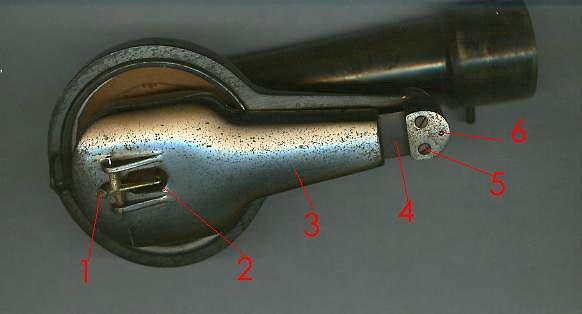
1. Hinge Block. There are two screws and an alignment pin that secure this part. There is also a screw that is inserted into the top (not visible in this photograph) that secures the whole hinge block assembly. This connection allows some lateral movement of the weight/stylus assembly to compensate for any eccentricity of the record.
2. Hinge Spring. This allows the weight stylus assembly to move in a vertical direction to allow even contact between the stylus and record.
3. Weight
4. Stylus Bar
5. Pivot Pin. This holds the needle bar in position. In this and subsequent photograph, the needle pin has been removed and temporarily replaced with a common straight pin for convenience of assembly/disassembly in this demonstration.
6. Limit Pin. This passes through a wire loop. The purpose of the wire loop essentially is to allow the stylus to be lifted off the record. Another purpose is so that you can easily gage stylus and reproducer position when adjusting the horn and reproducer heights.
7. Head Shell
1. Diamond Stylus.
2. Hook end of Stylus Bar.
3. Weight
4. Hinge Spring
5. One of two bottom screw that sandwich the hinge spring between the tow major parts of the hinge block.
6. Alignment pin.
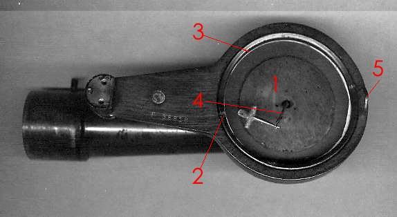
1. Diaphragm with cork damping - Laminated Rice Paper.
2. Threaded Retaining Ring.
3. Tabbed Retaining Ring.
4. Woven Silk Link - this is the mechanical connection between the stylus bar and the diaphragm.
5. Limit Loop
(Note: the order of installation of the diaphragm parts in the original
manufacturing process was threaded retainer ring; tabbed metal
ring; thin paper gasket; cork gasket; diaphragm; cork gasket; thin paper
gasket.)
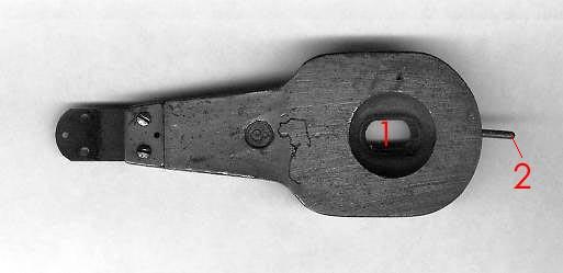
1. Link Pass Through Hole (top view of weight). On some earlier models (prior to 1915) there is a stylus bar mounting plate over this hole and the hole itself is very much smaller. Later models have the stylus mounting as part of the brass casting of the weight.
2. Limit Pin.
On the left are two additional screws that hold the hinge spring to
the weight.
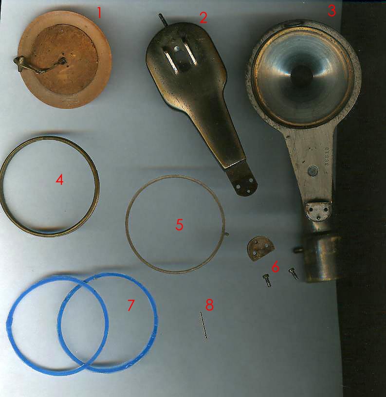
1. Diaphragm with link.
2. Weight - bottom view.
3. Head Shell (bottom view)
4. Threaded Retaining Ring.
5. Tabbed Retaining ring (this allows the threaded retaining ring to rotate without grabbing the gaskets and helps to apply even pressure.
6. Bottom plate of the hinge block with screws.
7. Diaphragm Gaskets. These are "experimental' silicon replacement rings of my own design and manufacture. Originally, they would have been cork and there would have been the thin paper spacer gaskets also. The paper gaskets are not necessary with modern neoprene replacement gaskets which produce a better air seal than did cork.
8. Pivot Pin. This is the actual pin. It can be a royal pain to remove
in some instances - we'll get to that in the rebuild section when I put
it up.
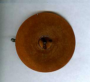
Top side of diaphragm. Note the ivory cone designed to distribute the force of the silk link as it acts on the diaphragm. This cone is a source of volume robbing air leaks. The solution to this will be detailed in the rebuild section.
Coming Soon: rebuild instructions.
Page Last Modified: 30 August 2003
