
Nowadays, digital 'Data Gloves' are commonly used in VR (Virtual Reality ) and , rarely, for M.I.D.I .control in a Live Performance situation. Are you frustrated not being able to use one with your analog gear?: Don't be...
The Analog Live Performance Gloves presented here uses 12 mercury switches :6 for the Left -hand and 6 for the Right- hand glove (these switches can be found at second-hand and surplus electronic stores).
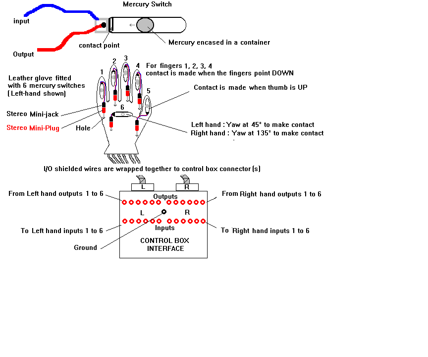
Construction:
Use a pair of old Black leather gloves and wrap 5 mercury switches on TOP of each finger using Black electrical tape. Also, attach a sixth mercury switch on TOP and in the middle of the glove (This will be used for angular 'Yaw' ).
Cut and Pre-tin 12 Blue wires and 12 Red wires (they should all be about 5" long).
Left-hand glove: Solder one end of the six Blue wires to each contact input of the six Mercury switches and the other end to the second contact of a 1/8" stereo mini-jack. Then, solder one end of the six Red wires to each contact output of the Mercury switches and the other end to the first contact of the 1/8" stereo mini-jack.Repeat the procedure for the Right-hand glove.
Drill tiny 1/8" holes through each glove, about 2" from the base of the switches (to accomodate the wiring).Cut and Pre-tin twelve 10' feet long shielded stereo cables (2 conductors+ Ground ).
Left hand Glove: insert six shielded cables through each 1/8" hole and bring the wires to the outside. Repeat the procedure for the Right- hand glove.
Pre-tin six 1/8" stereo mini-plugs and solder one end of the shielded cable (White conductors) to the plugs inputs. Then, solder the Brown conductor to the six plugs outputs.(Don't forget to connect the Ground wires to each grounding contacts of the six plugs. Repeat the procedure for the other glove.
Wrap all the shielded cables in a bundle and attach them together with plastic tie-ins. Solder the other ends of the shielded cables to two 13 Pins DIN connectors or one 25 Pins male DB-25 (RS232C connector): this connector will be used to connect the cables to the Control Box Interface.
Next step: construct a Control Box Interface consisting of a patchboard with 12 inputs/12 outputs jacks: you can use 1/4"or 1/8" Jacks (with Grounding) as required by your analog gear.. If you use banana jacks, you should also have an additional jack for GROUND. Then, drill a corresponding hole on the back of the box to accommodate the female DB25 chassis connector(s). Finally, connect all I/O wires internally to the various jacks.
Performance guidelines: Hereunder are some ideas on how you could use the two gloves simultaneously: For example: Use the Left hand glove for toggling between 6 different CV's and the right-hand glove for toggling between 6 different Clocks ( use it for gating Sequencers, S&H, Counters and Envelope Generators)...
Left-hand glove : Fingers 1 to 4: 16 steps sequencer CV outputs A ,B,C, D ; Finger 5 : overall VCA1 amplitude control; Switch 6 (Yaw) : Pan/Fade Left.
Right-hand glove:Fingers 1 to 4: CD4520 Dual Up-Counter outputs A ,B,C, D (multiple Clocks) ; Finger 5 : overall VCA 2 amplitude control; Switch 6 (Yaw) : Pan/Fade Right.(*)
Note (*): The sixth mercury switch contacts of the Right-hand glove should be pointing to the Right.
Use your imagination and discover new gestural techniques for live performances...
Enjoy...
![]()
