|
Ingredients:
-
Your favorite GS500e.
-
Phillips screw driver.
-
Racket wrench or equivalent + 10 mm and 7 mm sockets.
-
19 mm box wrench.
-
Vernier caliper or equivalent measuring device.
-
Dremel tool or small round file.
-
Pliers.
-
Wite-out pen or indelible marker.
-
Pen and paper.
-
Hammer (optional.)
-
Mosquito repellent and mosquito plant (optional.)
|
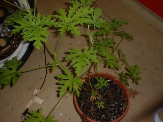 |
Spray liberal amount of the mosquito repellent on your whole body. Place the mosquito plant near the bike
for added protection. |
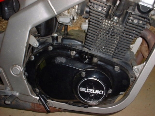 |
You will work on the right side of the bike, facing the brake pedal.
I swear it wasn't me who did those scratches on the cover. |
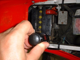 |
Remove the seat and disconnect the negative pole of the battery. |
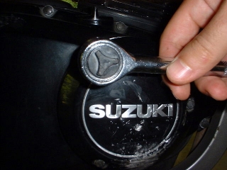 |
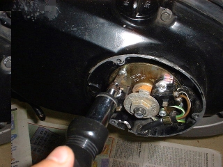
Remove the three bolts of the rotor cover with the 7 mm socket |
 |
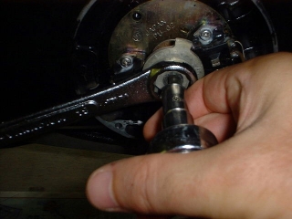
Remove the two screws that hold the rotor plate in place. |
 |
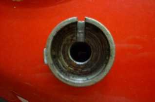
While holding the rotor with the 19 mm wrench, remove with the 10
mm socket the bolt that holds it. |
 |
This is a view of the other side of the rotor. Mine had a little notch in the keyway, although it cannot be seen in this picture. I wonder how that happened. |
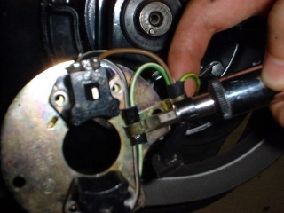 |
Unscrew the electrical contacts, remove them, including the magnets, and open the clip that holds the wires. |
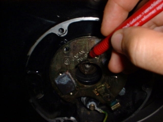 |
You want to rotate the place counter-clockwise by 5º. With an
indelible marker, draw an arrow in the direction that you want to turn it so that you don't get confused later.
I found that my marker was not as indelible as it claimed to be, so later
I used Wite-Out. |
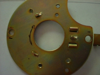 |
The distance between the center of the two holes is 7 cm. That means
that 5º is equivalent, at the level of the screw holes, to (5*70mm*pi)/360 = 3.05 mm. Measure with the
vernier caliper a distance of 3 mm from the screw holes in the direction
opposite to which you want to turn the ignition plate, and mark it with
the marker.
See the two little black marks near the holes? Note that this picture shows the back of the plate, so that the arrow is pointing clock-wise. |
 |
Remove the clip on the front of the plate.
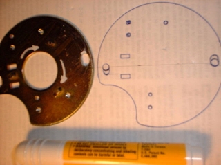
On a sheet of paper, take a blue-print of the plate, and mark
the point that you want to file up to on the blue print too, so that you can compare it later in
case the marks you made on the plate get deleted. Don't ask how I figured this out.
Now, using a your favorite grinding tool, start filing the slots. A
dremel tool would be very helpful since the metal is thick and hard. I
don't have one (it's on the Christmas list though,) so I used a small file.
It took me about 1 hr.
Remember to measure often and compare to your blue-print.
In the picture on the left you see the plate once finished. Notice how the holes are slotted now, and compare it to the blueprint on the paper sheet.
|
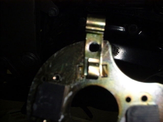 |
The last thing to do is to bend the clip for the wires. This is actually
what took me the longest time. Filing it is not an option because the side
is too thin. I used the hammer at first and then bent the two little feet with
pliers.
Now put everything back together. Before installing the cover, start the bike and make sure that the rotor is turning freely and does not hit anything.
While you're on that side of the bike, check the level of your oil also.
Don't forget that the bike must be on the centerstand, or else you may
overfill it. Not that I have ever done that...
Q. "Does it work?"
A. Truthfully, I don't know. I have no idea how to measure the
actual timing on this bike.
Q. "I see, but in terms of horsepowers?"
A. I don't know, I don't have access to a dynamometer. It would
be really interesting if someone could compare before and after.
Q. "Ok, but in terms of seat-of-the-pants-type horsepowers?"
A. Oh, is that what you meant?! I have been out for a short
ride on the day after. It felt like it pulled a little more below 4k rpms
and seemed to climb hills with more ease. But then it does so also after
I give her a nice bath ;)
Thanks to Martin, Srinath and the other folks on the board at www.gstwin.com
for helping out with directions. |