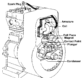
Two basic type of ignition systems are used:
1. A flywheel type, having either an internal or external breaker system.
2. The Magna-Matic system, having the armature and rotor beneath the flywheel, and an external breaker system.
Check Ignition
Remove the spark plug. Spin the flywheel rapidly with one end of the ignition cable clipped to spark gap tester with the other end of the tester grounded on the cylinder head. If spark jumps the .166" tester gap you may assume the ignition system is functioning satisfactorily.
NOTE: If engine runs but misses during operation, a quick check to determine if ignition is or is not at fault can be made by inserting the tester between the ignition cable and the spark plug. A spark miss will be readily apparent. While conducting this test on a Magna Matic equipped engine, Models 9, 14, 19 and 23 set the tester gap at .060".
SPARK PLUG
The plugs recommended for Briggs and Stratton engines are as follows:
1 ½" Plug 2" Plug
CJ-8 J-8 Champion
A-7NX A-71 Auto-Lite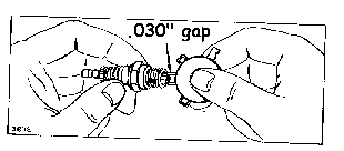 CS-45 CG-46 AC
¾ " 13/16" Plug wrench (deep socket)
Spark plug Cleaning.
Clean spark plug with a pen knife or wire brush and solvent and set gap at .030" for all models. If electrodes are burned away, or the porcelain is cracked, replace with a new plug.
Ignition Flywheel Type - Internal Breaker
The flywheel is located on the crankshaft with a soft metal key. It is held in place by a nut or starter clutch. The flywheel key must be in good condition, to insure proper location of the flywheel for ignition timing. Do NOT use a steel key under any circumstances. Use only the soft metal key, as originally supplied.
The keyway in both flywheel and crankshaft should not be distorted. Flywheels used are made of aluminum, zinc, or cast iron.
Remove Flywheel nut or Starter Clutch
On flywheels of 6 ¾" diameter or less, use a flywheel holder to keep flywheel from turning. On rope starter engines, the ½" flywheel nut has a left-hand thread and the 5/8" has a right hand thread. Starter clutch used on rewind and wind-up starter has a right hand thread.
ON flywheels of larger diameter, place a block of wood under flywheel fin to prevent flywheel turning while loosening nut or starter-clutch.
 Remove Flywheel:
Some flywheels have two holes provided for use of a flywheel puller. Use puller shown in photo. Leave nut on rope starter engine for puller to bear against. Small cast iron flywheels do not require a flywheel puller.
Removing Breaker Cover:
Care should be taken when removing breaker cover, to avoid damaging cover. If cover is bent or damaged it should be replaced to insure a proper dust seal.
Breaker Points.
Breaker point gap on all models is .020". Breaker points should be checked for contact and for signs of burning or pitting. Points set to wide will advance spark timing and may cause Kick back when starting. Points gapped to close retard spark timing and decrease engine power.
Remove Breaker Points Breaker point assemblies of style shown in Photo are removed by removing condenser and armature wires from breaker points clip. Loosen adjusting lock screw and remove breaker point assembly.
Ignition Flywheel type Internal Breaker:
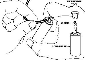
Breaker point assemblies of style shown in photo are removed by loosening the screw holding the post. The condenser on these models also includes the breaker point. The condenser is removed by loosening the screw holding the condenser clamp.
If the breaker point plunger hole becomes worn excessively, oil will leak bast the plunger and may get on the points, causing burning. To check, loosen breaker point mounting screw and move breaker points out of the way. Remove plunger. If the flat end of the plug gauge will enter the plunger hole for a distance of ¼ " or more, the hole should be rebushed.
Install Breaker Point Plunger Bushing.
To install the bushing, it is necessary that the breaker points, armature and crankshaft be removed. Use a reamer should be in alignment with the plunger hole. Drive the bushing until the upper end of the bushing is flush with the top of the boss. Finish ream the bushing with reamer. All remaining chips or dirt must be removed.
Breaker Point Plunger: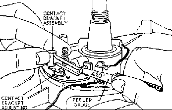
If the breaker point plunger is worn to a length of .870" or less, it should be replaced. Plungers must be inserted with grove at the top when installed or oil will enter breaker box.
Install Breaker Points.
Insert breaker plunger into the plunger hole in cylinder. Breaker points as shown in Photo are installed by placing the mounting post of the breaker arm into the recess in the cylinder so that the grove in the post fits the notch in the recess. Tighten the mounting screw securely. Use the ¼" spinner wrench if available. Slip the open loop of breaker arm spring through the two holes in the arm, then hook closed loop of spring over the small post protruding from the cylinder. Push flat end of the breaker arm into the groove in the mounting post. This places tension on the spring and pulls arm against the plunger. If condenser post is threaded, attach the coil primary wire (and ground wire if furnished) with the lock washer and nut. If primary wire is fastened to condenser with spring fastener, compress spring and slip primary wire and ground wire where furnished into the condenser post. Release spring. Lay the condenser in place and tighten the condenser clamp securely. Install spring to breaker arm as shown in photo.
When installing breaker point assemblies, as shown in the photo, be sure the small boss in the magneto plate enters the hole in the point bracket. Mount points to magneto plate or cylinder with lock screw. Fasten the armature lead wire to the breaker points with the clip and screw. If these lead wires do not have terminals, the bare end of the wires can be inserted into the clip and screw tightened to make a good connection. Do not let the ends of the wire touch the point bracket of magneto plate or ignition will be grounded.
Flywheel Type Internal Breaker:
Adjusting Breaker Point Gap
Turn crankshaft until points open to widest gap. When adjusting breaker point assemblies as shown in Photo. Move condenser forward or backward with a screwdriver until a gap of .020" is obtained. Breaker points assemblies as shown in Photo are adjusted by loosing lock screw and moving contact point bracket up or down. Gap is .020".
NOTE: Always clean breaker points after adjustment. Open the points and insert a piece of lint-less paper. Draw the paper through the points. Open points when removing paper so it will not tare, leaving paper between the points.
Breaker Point Cover:
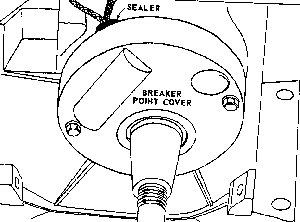
The breaker point cover. Photo protects the points from dirt. The opening for the primary and or ground wire should be sealed with NO. 2 Permatex or similar sealer to prevent dirt from entering the breaker box. Cover should not be distorted so as to lose its seal around the outer edge. Replace if damaged.
NOTE: Engines used for winter applications use vented breaker covers.
Install Armature:
Install governor blade and armature. Photo the mounting holes and the armature laminations are slotted. Push armature up as far as possible and tighten one mounting screw to hold armature in place.
Adjust Armature Air gap: Three styles of armatures have been used. Set air gap between the flywheel and armature in table. With armature up as far as possible and one screw tightened, slip a proper gauge between the armature and flywheel. Turn flywheel until magnets are directly below the armature loosen the one mounting screw and the magnet should pull the armature don firmly against the thickness gauge. Then tighten the mounting screws.
Install Flywheel, Nut and or Starter Clutch:
Remove all oil or grease, clean flywheel hole and tapered end of crankshaft before assembling flywheel to shaft. Insert zinc key into keyway. Slip spring washer over crankshaft with hollow side toward flywheel. To tighten flywheel nut or starter clutch, reverse removal operation described earlier. Torque to specifications.