
Custom disc brakes for the Sunline - page 1Well since the disc brakes on the Caboose worked so well, I just had to find a way to put disc brakes on the Sunline. The Sunline has a Hayes 3000# axle with 10" x 1 5/8" electric brakes, which I found was discontinued in 1993. I could have just bought a new 3500# axle and disc brake assemblies, but like with the Caboose I wanted a challenge.The first thing I needed was to find a source for used idler hubs, because nobody sold a new hub with a 1 1/4" inner and 1 1/16" outer bearing set. No luck at all finding used ones either. But after examining the drum hubs, I found that it would be better to just modify what I had. There would be 1 inch of hub flange thickness, and the rear of the hub was already machined nice and flat for the brake magnets if I wanted to mount a rotor to it.. I took the hubs to work, and first had the drum part torched off around the 7 1/4" ridge on the hubs. Then I put them in the lathe and turned them to 6 1/2". Pretty simple. I also had to consider if I was going to upgrade the wheels or not, because that would determine how big of a rotor I could use. I decided to stick with the factory wheels for two reasons. First, I had just bought new 14" tires and had them mounted. Second, I wasnt sure if I could trust automotive wheels to carry 3000# per axle. I looked and looked and could not find weight limits anywhere. So, using the same thin profile calipers I used last time, I could use a 10 1/2" rotor, or maybe a 10 3/4" one but thatd be really pushing it. The only rotors that I know of that will fit over a 6 1/2" diameter hub are the ones I used last time which are way too big. The rotors from Kodiak brakes would fit, but they would probably be too deep since my 3000# axle also has a hub face to brake flange distance of 1/2" less than a 3500# axle. And I couldnt just locate the assembly back further, since the trailer body and frame sit so close to the axle. Locating the rotor on the back of the hub would give me tons more selection. Which I needed because to make everything fit I would need a rotor with a 5/16" hat height but as thick as possible. I eventually found the perfect one. The rotors from the early style GM W-body cars (Lumina car, etc) are 10 1/2", are 1" thick (thicker than any disc brake packages you can buy), and have a 115mm bolt circle which is very close to 4 1/2". I wanted minimum modification to the rotor, and all I had to do was open the center hole from 2.76 to 3.02, and open the drilled holes to ___ to allow the wheel stud knurls to center the rotor. I needed to replace the existing wheel studs with ones about 1/2" longer (1/4" for the rotor, 1/4" for the counterbore in the hub that would no longer be used), with one condition. The knurl had to be that much longer so it would engage in the hub the same amount as before. I ended up finding the perfect wheel stud from a Raybestos catalog I won off ebay. I wouldnt have found it otherwise - it comes from a 1946-1960 Chevy 3/4 or 1 ton truck. Then for peace of mind, I decided to fill the counterbores in the hubs with steel to increase the amount of knurl engagement. I bought a piece of 13/16 round stock and cut it into 1/4" spacers. The counterbores measured from .809 to .818. The round stock is .807 which is perfect. Before cutting the spacers, I predrilled the stock in the lathe to 3/8". I used an epoxy for metal to secure the spacers in the holes. Once it dried, I drilled the spacers through the existing holes to line up the holes. Then I had to enlarge the holes just a bit more, since the old wheel studs measured .540-.545 and the new ones .550-.555. I emailed the wheel stud manufacturer and they agreed that if I left the holes alone it would be excessive press. But the next size drill (out of ALL drills) was .547, which would be way too big. So I looked to McMaster-Carr and they stocked a .543 reamer. That would give me almost the same press fit with the new studs as the original holes had with the original studs. So I reamed the holes, and I was all set. I resprayed the hubs black and baked them in the oven. After installing new bearing races for peace of mind (the old ones were a bit yellowed), I attached the rotors to the hubs with the studs, which I drove home with a torque wrench, a few old lug nuts, and some grease to keep from tearing up the threads. Never did I get to 100 ft lbs except when I got to the end. Now it was time for the caliper attachment plates. The clearances in the last trailer were wide open compared to this one. The axle flange was an oddball one too. Unlike new brake assembles which have everything mounted to a plate that mounts to the brake flange, this axle had only the shoes mounted to the plate. The pivots and stops were all welded to the axle flange, as was the brake assembly itself. No bolts. So first I had to grind the welds down and break the plates off with a sledge hammer. This revealed a 3" x 6" plate similar to a brake flange but without holes. Then I had to grind off the stop block at the bottom. The magnet arm pivot would be ok since it would nest inside the rotor hat, as well as help locate and support the new caliper mounting plate. The only way I could make the plates fit was to design one to bolt to the axle flange, and the other to bolt to the first one and butt up to the axle flange. This would apply all of the braking force directly to the axle flange and would leave only the job of holding the plates down to the bolts. This is also why I decided on locating the calipers on the front side of the flange. Calipers on the rear side is usually more preferable (because of plumbing safety), but the geometry of locating the calipers on the front places the braking force on the long edge of the axle flange. I felt this was a better design. The first plate and all the mounting bolts would have to totally nest inside the rotor hat. Because the rear of the hub sits 1/2" from the flange, I would have to counterbore the two bolt holes closest to the spindle. The other bolts I set further away for extra support. These had to be closer to the middle in order to clear the structural welds on the rear of the flange. I decided on 3/8-24 bolts, Grade 8 of course. The other trailer had 7/16" bolts, but since there will be no shear loads on these bolts, I figured 3/8" was fine since it was about the largest I could fit anyway. Another issue was the caliper clearance in regards to the trailer. It is close. There is a 3/4" offset where the trailer frame and body meet, and I had to take advantage of this because otherwise the caliper bolts would not have enough clearance to assemble to the plates. The only way to make this work was to "roll" the caliper down until the caliper was 3/4" lower in the vertical direction. I examined the caliper construction, and at this angle the caliper should still be fully bleedable. If not I can always dismount it temporarily. I had the plates made on the burn table at work, out of some scrap 3/8" mild steel plate. I final drilled and tapped the holes, did the counterbores, and sprayed them black and stuck them in the oven just like the hubs. Then I was ready for assembly. I did a test fit of everything before greasing the bearings. Allowing for .03 of bearing race seating, the counterbore bolt heads came .06" from the back of the hub. This should be fine. I can always grind down the bolt heads slightly if I need to later. I didnt want to go any deeper with the counterbores because I wanted to leave enough material to keep good strength. I left 3/16" for those 2 bolts. Everything else fit just fine. I had to clean up the edges of the axle flanges with a grinder so the caliper plate would sit tight against it. I installed both plates and torqued the bolts first. Then I packed the new bearings with disc brake wheel bearing grease, and installed them along with the new seals, then installed the hubs to the spindles and seated the races. Then I cleaned the rotors, and installed the calipers with new full organic pads. Just like the other trailer, this should keep the pads from rusting to the rotor during long periods of nonuse. Just like the other trailer, I had to tighten the caliper bolts with channellock pliers. And just like the other trailer, they shouldnt come loose. The shape of the plates on both trailers makes the plate carry the braking load. The bolts simply have to hold the caliper to the bracket. I tried on a wheel to see how everything fit. It all fit just like it was supposed to. The caliper comes about 3/16" from the wheel, just like the other trailer. The wheel area is pretty much done, now I just need to do the hydraulic system. I still have not decided on hoses, but looking in the Raybestos catalog, it looks like Astro van front hoses are the way to go. Either that or 79-80 Monza front hoses, or 83 Camaro rear hoses. All this will be plumbed up front to a Hydrastar just like in the Caboose. I am still debating whether or not to get another Hydrastar on sale, or go with boat trailer brake line quick disconnects and swap Hydrastars between the trailers. If I ever want to sell the Sunline, Im going to want the Hydrastar to be there, or put on a 3500 axle with electric brakes. Also, this Hydrastar will probably not be as fancily enclosed. Ill probably just put it in a cheap box and mount it in the battery area.
|
 A sketch of what the brakes used to look like.
Sorry I didnt get a shot of the original assembly, but here it what it is. I also have a picture of the inside of the drum, but seem to have lost it somewhere. These pictures were all taken with a garage sale Polaroid camera. Some pictures turned out with a major pink tint, so I tried to adjust the color the best I could.
|
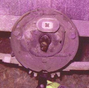 A view of the underlying brake assembly.
Nasty old electric brakes, and I still really dislike drums. "Ugly as a bucket of rusted bolts" - good quote about drum brakes from another website. Discontinued since 1993, and shoes not available anymore, these brake assemblies are better off not on here. In this picture you cant see the black widow spider that had been living in there since I got the trailer. Sorry Charlotte, you need to find a new home.
|
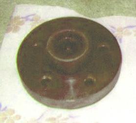 The hub, with drum removed.
Here is a view of the back side of the hub, after torching off the drum and cleaning up the outside to 6 1/2" diameter. You can also see the counterbores where the wheel studs heads used to sit. These I filled in later to give the studs 1/4" more knurl engagement.
|
