
The Caboose gets its own set of custom disc brakes.Well now it was time for the next project. One of the considerations when I bought the trailer was that it had provisions for future brakes. True, the trailer is only 900# empty and probably never exceeds 2000#, but my 6000 isn't exactly a heavy duty truck either. And with the wife and kids in the car, I wanted all the control I could get in a panic stop, or when the roads got slippery. For those reasons, along with the burning desire to take on the project anyway, the Caboose was getting its own brakes. I have a strong dislike for drum brakes of any kind (I upgraded both the 6000 and my wifes Celebrity rear brakes to disc), so hydraulic disc would be the only way to go. I also wanted full control over the hydraulic discs, so an electric-over-hydraulic actuator was the only way to go.I began to collect my parts over the winter. I first researched actuators, and the choices came down to an Ausco TrailrBrakr or a Carlisle Hydrastar. I went with the Hydrastar because of the lower price and because of the well-known company reputation. I dug around the internet (found prices from $300 to $700), and asked around locally (not a soul here had even heard of it). I ended up getting a deal on the Hydrastar from "The Expediter" in Florida. Even though he said it was his last one and the ad is still running, I still havent found a better deal than the $300 I paid for the whole package which included the breakaway package. Still, $300 is a lot for me. I wanted the unit to be well protected. So I designed an enclosure in the front "A" part of the trailer frame for the actuator and battery box. Later I would find that I could also keep the battery charger, extra brake fluid with special homemade funnel, small tools, and whateer else I needed to carry along in there. Meanwhile, I spent a ton of time researching brake rotors to find what would fit over the 6 1/2" diameter trailer hubs. My only answer came from Parts Mike the Answer Man. The rotors would be the slip fit 1" thick rotors from the 1988 and up Chevy 4x4 trucks (standard cab only). The rotors had a 655 bolt pattern, so I redrilled them for a 545 bolt pattern at work. I also turned spacer collars on the lathe to take up the difference between the rotor center hole and the trailer hub. After that I ran into a stumbling block. I discovered that one rotor had a face thickness of about 1/4" and the other 5/16". I made my spacer collars at just under 5/16". With two brand new rotors purchased simultaneously from Auto Value, they should have been the same. I didnt know what to expect later. So I made two shim spacers out of 14ga steel, and used one to make up for the lack of face thickness on the thinner rotor. I still have the other one in my trailer file in case I need to replace the rotors later on and they both end up being the thinner type. The next consideration (which tied in with the rotors) was brake calipers. The 6000 normally carries a 14" wheel with a 10 1/4" brake rotor (therefore an 11 1/4" rotor would fit under the 15" wheel). The Chevy rotors were 11 5/8", so I needed calipers with a very thin cross section in order to clear my wheels. After taking many measurements over and over, I found that with a Pontiac 6000 caliper, the 1" thick wheel adapter and 5/16" brake rotor face would just allow the caliper to clear the wheel, with maybe just a touch of grinding. I thought a lot about integrating a parking brake too, but the only thing I found to fit the setup was early 80s Buick Riviera rear calipers which have too thick a cross section to clear the wheel. Im still thinking about it though. Now for the backing plates. My first thought was to cobble some rear backing plates from a Pontiac 6000 STE. But I figured with the amount of work Id put into cobbling the plates, I could have some nice plates made at work on the burn table that would fit perfectly. So I took many calculations, and designed the plates. Because of such limited clearances, I had to made the plates a two-piece design. I joined everything with 7/16 fine thread grade 5 bolts, except for the caliper bolts which are 11mm x 1.50. I primed and panted the plates, and everything assembled and fit like it was meant to be there. The hoses were the next consideration. I thought of using standard trailer hoses and banjo fittings, but the banjo fittings alone would have cost more than complete automotive hoses. I found that the hoses from an 89 Bonneville would fit perfectly, and the mounting bracket would even fit perfectly after a slight modification. I straightened the bracket and enlarged the mounting hole to fit one of the 7/16" bolts in the caliper brackets. I also had to file the brake line ends of the hoses down to true 5/8" diameter circles. The hoses came with some funky shapes for a foolproof fit into the Bonneville brackets. I made my own brackets out of an old muffler hanger that I never used. Just drilled out one hole to 5/8", skipped a hole, drilled the next hole to 3/8", and used the hole between them for a nice clean right angle bend using pliers. I bought some standard brake hose clips, the hard brake line (standard 3/16" automotive line) and fittings, and was ready to go. On final assembly, I decided to grind just a smidgen off the inside tips of the calipers. I didnt have to, but I wanted the edge of the brake pads to line up with the edge of the rotors for a cleaner look and operation. I still would have 3/16" between the calipers and wheels, which is tight engineering, but plenty of clearance in reality. Once again, I assembled everything with anti-seize on all the hub parts. I swear there is more engineering in this area than in the whole trailer! First I had to loosely assemble the brackets, then assemble the brackets to the brake flanges and tighten everything. Then onto the hub I slid the rotor, the spacer collar, the shim spacer on the thin rotor side, then the wheel adapter, and tightened that all down. Then I attached the caliper, removing the rubber caps and using channel lock pliers to tighten the bolts because there was no room for a brake socket. Then I added the brake hoses and lines under the trailer to a "T", then one up to the actuator up front.. Now was time to make the front enclosure. I cut out a bottom piece for the enclosure from a scrap of 11ga steel from work, and had it bent up to make a pan that would fit in the front "A" frame of the trailer. I cut out passages for the wire and brake line, and drilled and tapped it to the trailer frame (which was 3" high). To build up the sides of the box so that the 5 1/2" tall Hydrastar would fit, I used scrap aluminum channel from work. It is also available at Home Depot. I cut these pieces to the correct angles, and secured them to the trailer frame with 10-24 studs. I cut another piece of 11ga steel for the lid, and hinged it. The knob is available from McMaster-Carr. I wanted the knob to be retained in the top cover when it was loosened, so I drilled and tapped a 1/4-20 hole through a 3/8 bolt. A 1/4" bolt secured vertically in a bracket over the Hydrastar allows the lid to be tightened down, while the knob that spins freely in the cover. I added weatherstripping around the top of the aluminum channel, and caulked all joints in the enclosure for a good seal. Bleeding these brakes was a cinch, since the Hydrastar acts as its own automatic pressure bleeder. I was concerned at first that the Hydrastar only put out 200-600 psi, and car systems (and other actuators) put out 800-1200psi. But all that changed when I went to leave the driveway for a test drive. I had to turn the Hydrastar all the way down to 200psi to keep the brakes from locking up. I took the trailer to the old Wolohan parking lot, where I found they lock at about 300psi. So there is plenty of reserve available for when the trailer has a load. I ended up buying a Tekonsha Envoy inertia controller to apply the brakes proportional to how fast the car attempts to stop. The Envoy is one of the few truly proportional brake controllers, and also has a large front knob so I can easily adjust the power setting on the fly. Around here the road conditions can change suddenly anytime, and I need that kind of control to turn down the power when the roads get slick. Of course I had to find a place to mount the controller. There was basically no place to mount the Envoy in my crowded dash of gadgets. I thought of mounting it on the roof, but I didnt want to screw anything up. I finally found the perfect place, which is between the cupholder and the cb radio. I made a bracket out of a piece of scrap stainless steel and a piece of aluminum channel to mount the controller to my console without drilling into it. It seems to be pretty solid, and I can reach everything on the controller nicely. The brakes work very nicely. Actually, the 6000 stops better WITH the Caboose on than without. It used to be the other way around. Of course it makes sense since the Caboose brakes are more heavy duty than those on the car. Looks like they should give me years and years of trouble-free service.
|
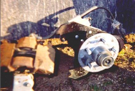 Axle and hub, with the plates installed.
Sorry I was only able to take these pictures after the brakes were in service for awhile. Had to wait for it to warm up some outside. So I did my best to disassemble things for now. I left the hydraulic system intact for now too, but you can get an idea as if it wasnt there. Also sorry for the dirt. It didnt look this dirty in reality. The camera flash must have enhanced the dirt. This view shows the axle and hub, with the plates assembled to the brake flange. I had to retorque the plate bolts after awhile, so I didnt want to take them apart and have to start over. I can post the cardboard templates I used so you can get an idea. The primary plate (which the caliper mounts to) is visible here.
|
 Another view of the axle, hub, and plates.
This view shows the secondary plate. This plate attaches between the axle and primary plate. Both plates have cutouts for the axle. The primary plate has a relief area where the rear of the hub is close by. The secondary plate has relief cutouts for the little standoffs on the brake flange. To me those are a bad idea, especially having them inside the bolt circle. What will happen when you tighten the bolts that are on the outside of the standoffs? Correct, the plate and/or the brake flange will bend. So the relief cutouts make the secondary plate sit truly flush onto the brake flange. The brake hose is also shown well in this view. Also shown well is the bracket that I made, securing the hose to the frame where it connects to the hard brake line.
|
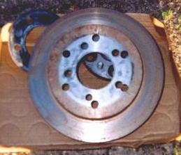 Brake rotors, as modified.
Here is a view of one of the brake rotors. The original 655 pattern is visible, as well as the 545 pattern that I drilled. The silver center is from the anti-seize that I left on everything. No sense wiping it off just to reapply it, so I just left it on in all the photos.
|
