|
|
| While the Germans were developing pure axial flow turbines just prior to WWII, Whitney and the British were developing a centrifugal-axial flow turbine. (similar in design to Figure 3) |

|
|
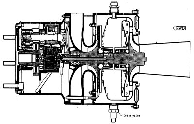
The third type of conventional turbine uses
centrifugal wheels both for compressing air and for the hot or working
stage. (Figure 4) Work is extracted in this type of turbine using a
combination of impulse and reaction forces on the hot rotor. (mixed
flow) |
|
Tesla Turbine Design
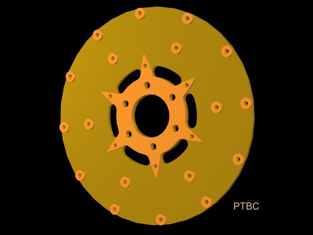
Tesla stated that the round washers placed around the outer perimeter were absolutely necessary for start-up torque, and to give an advantage under highly loaded conditions. Understanding how the geometry of this outer periphery region interacts with the nozzle and the fluid passing through the nozzle is the key to disk turbine efficiency.
|
|
| When Tesla was developing his turbine, a working knowledge of aerodynamics was held by very few people around the world. Even Tesla know very little about the subject, but he knew from extensive experiments what did and did not work. (Figures 6 & 7 show Tesla's inlet nozzles) Today we have a much better understanding of the key role aerodynamics plays in turbine design and operation, and this is the area where we can make relatively small changes to the basic design and obtain great improvements in performance. |
|
Phoenix Winglet Design
From the LabsIn our experiments we built up two disk packs which were identical in every way except for the geometric shapes placed between the disks. The "control" disk pack was built to Tesla's specs (using a spacing of 0.125 inch between the disks) and was used to compare experimental variations in the second disk pack. We used a small air compressor to charge a 20-30 gallon tank to 100 psi for each test cycle. A frequency counter was used in conjunction with our custom built Hall-effect shaft rotation detector to compare runs. As long as every run begins with the same air pressure (100 psi), the disk pack configuration yielding the highest rpm is the most efficient. While I won't go into much detail this month concerning test results, here is a brief summary:
|
|
a) Tesla configuration |
|
average peak rpm: |
1520 |
| b) Phoenix winglets at 37 degrees angle of attack | |
|
average peak rpm: |
2040 |
ConclusionsUsing a winglet in place of the outer periphery round washers of Tesla's design, we were able to gain approximately 30% higher efficiency. Based on other experimenter's test results with direct combustion and the Tesla configuration, we should expect our overall fuel to shaft efficiency to come in around 31% -- placing our design right between gas piston and diesel piston efficiencies. Beyond TeslaNext time we'll have photos of our test bed setup, and will discuss in more depth the aerodynamic differences between Tesla's original design and the Phoenix improvements. Till then, keep moving forward. We've got the sticks-in-the-mud on the run! Ken Rieli |
Questions? Comments?
prieli@up.net
Last updated: 04/29/02 04:20 PM

 After
we achieve a supersonic flow of gas through the nozzle, the next
challenge is to convert the highly energetic gas into work. Early bucket
type turbines operated almost completely by impulse -- by the working
fluid impacting the bucket. Today's axial flow turbines use blades
mounted perpendicularly to a central hub, and rotate perpendicularly to
the flow of gas through reaction -- or changing the direction of fluid
flow. (Figure 2)
After
we achieve a supersonic flow of gas through the nozzle, the next
challenge is to convert the highly energetic gas into work. Early bucket
type turbines operated almost completely by impulse -- by the working
fluid impacting the bucket. Today's axial flow turbines use blades
mounted perpendicularly to a central hub, and rotate perpendicularly to
the flow of gas through reaction -- or changing the direction of fluid
flow. (Figure 2)