My Pictures so far. Ignore the dates as the camera isnt set yet! Pictures with the blue border are clickable, just hit back to come back here (you will increase the access count at the bottom this way, it is better to right click and "open in new window"
So far I have gotten 3 or 4 view pictures from all over the web, and converted them to a sorta 1/6 scale and then taken some basic measurements from there to create my nightmare.
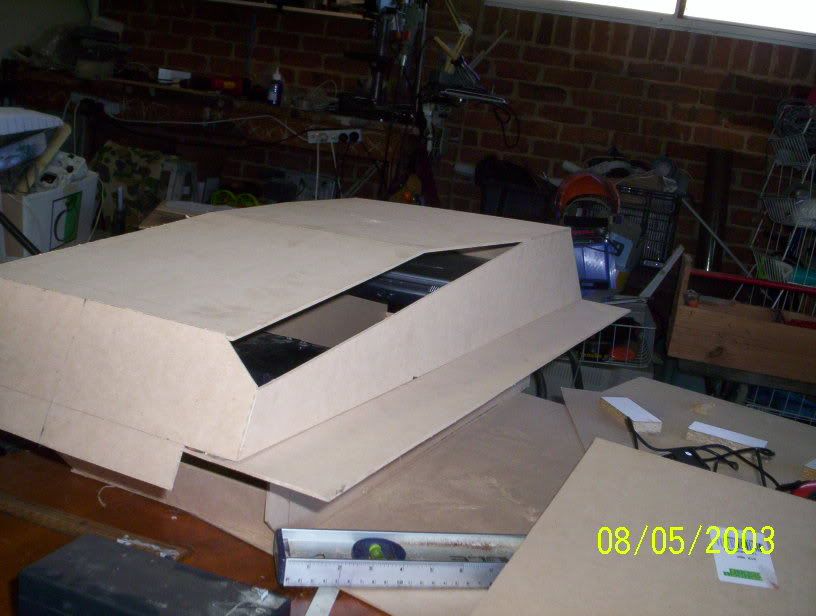
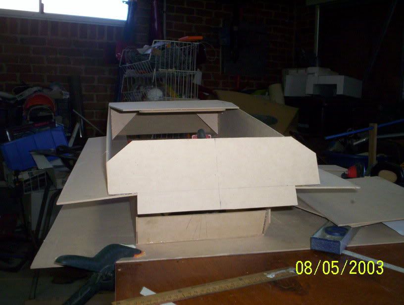
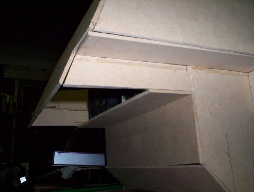
The Pictures below show my templates made from 3mm MDF and held together with hot glue. Now to take it apart and get a friendly metal shop to cut them out in either steel or aluminium (still not sure what yet)
 Picture 1
 Picture 2
 Picture 3
 Picture 4 (possible engine configuration)
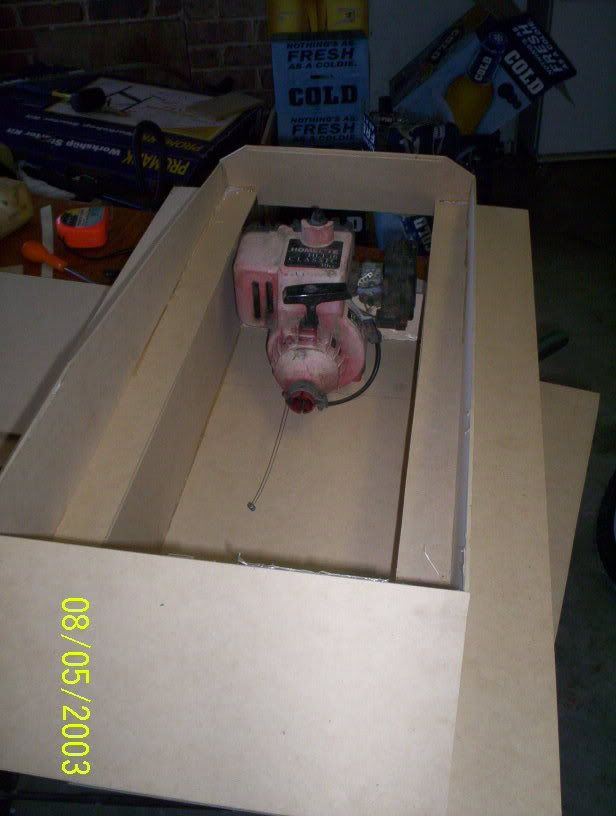 Picture 5 (30cc Whipper Snipper Motor)
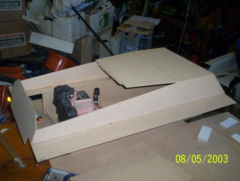 Picture 6 (2 stroke motor)
 Picture 7 (nice butt view)
 Picture 8
 Extended the side to reach the Rear Plate
 Possible location for extraction Fans (like the real thing)
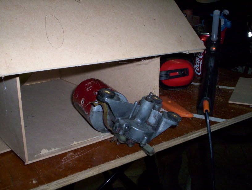 Lots of room for the electric option
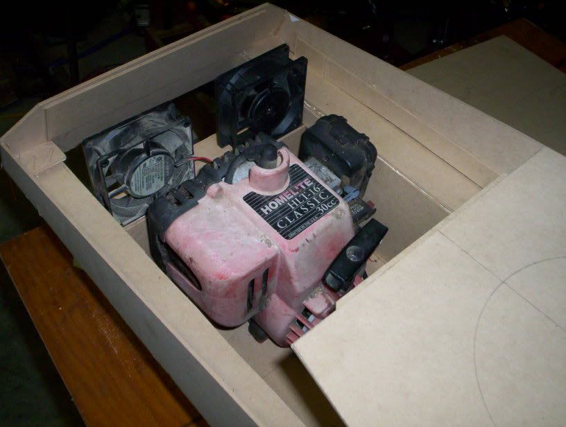 Lots of room for the Petrol option also
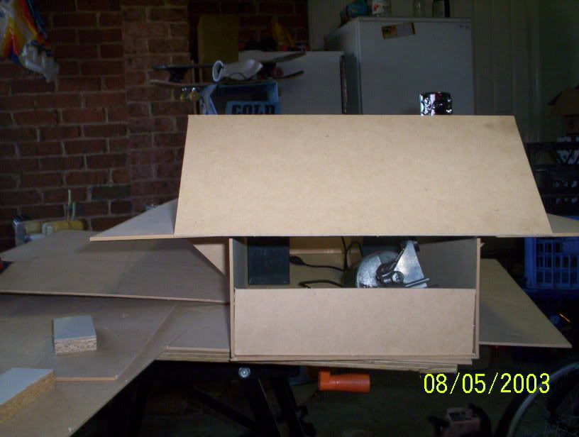
 Head room for the petrol Motor
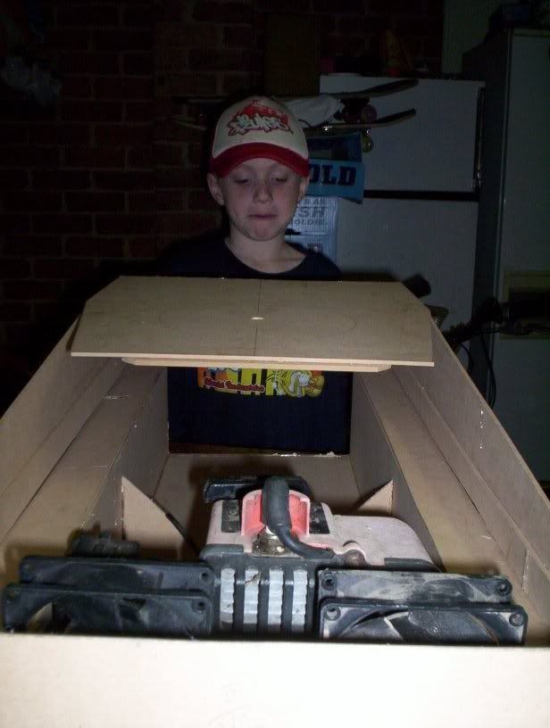 One of my helpers
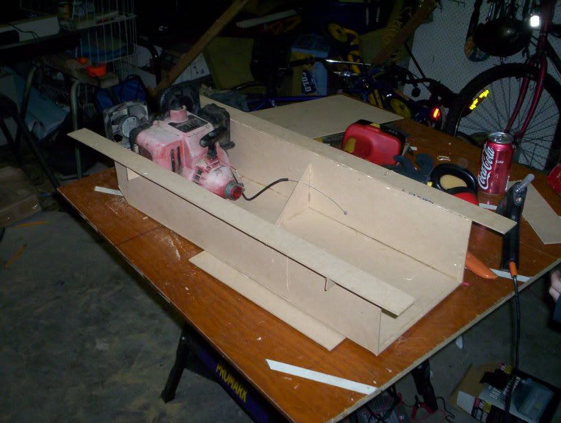 There will be lots of space for either motor option
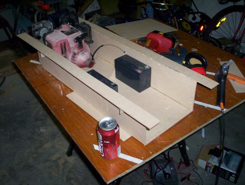 enough room for both motor options (now theres an idea)
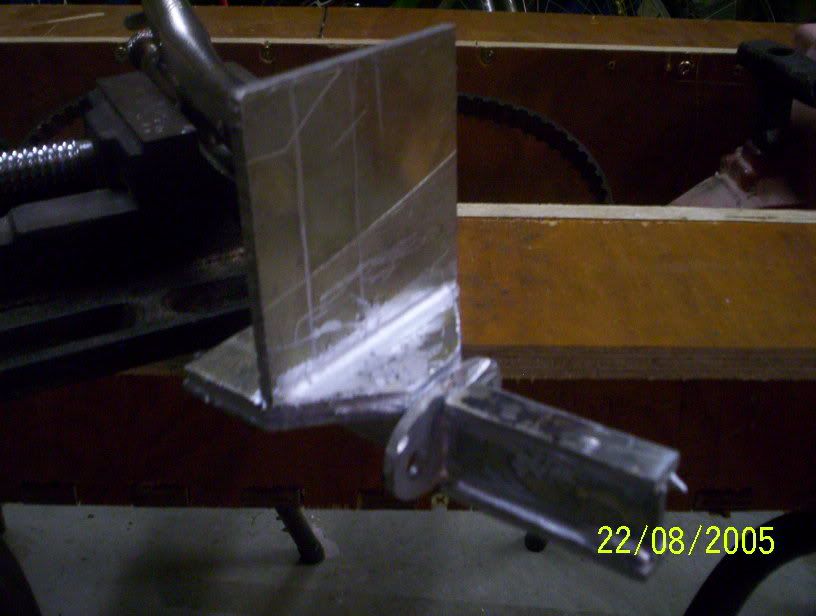
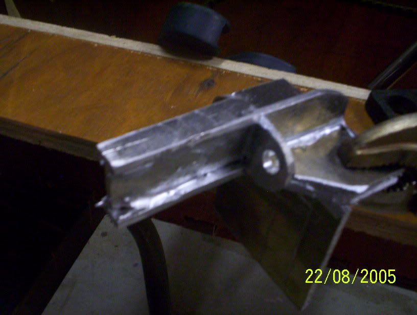
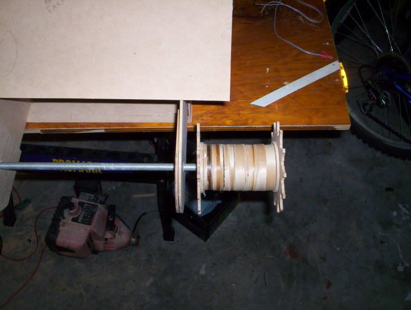
 Sides for the transmission housing and the sprocket and hub
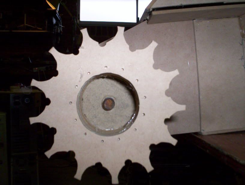 sprocket
 sprocket and hub on Hull
 Closeup of sprocket and hull
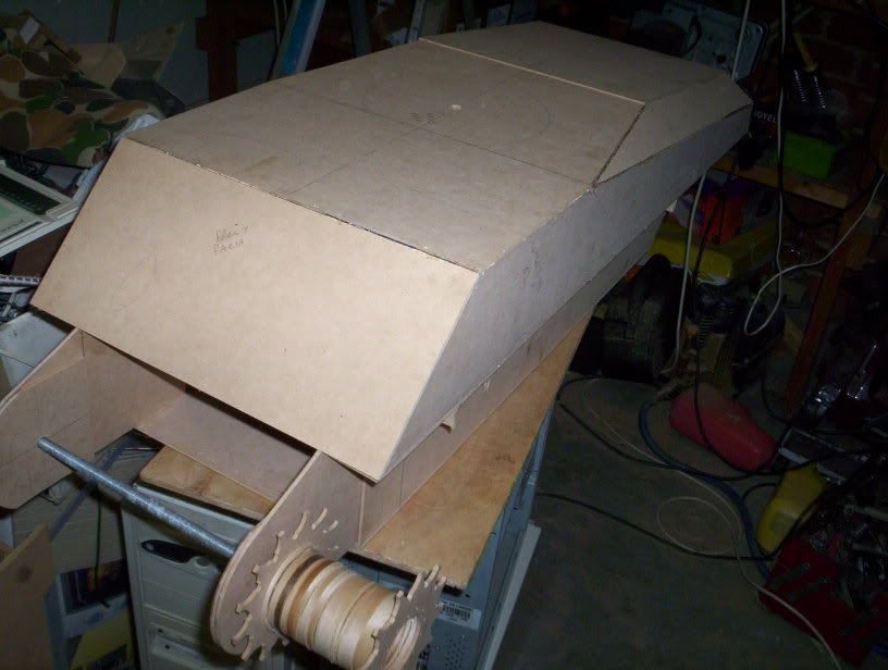 How it looks so far
I have updated the pictures to be clickable.
I now have the sacrificial victim (laptop) that will become the Brain of the control system. Dick Smith electronics have come to the party by allowing me to purchase a K-2805 Parallel Port Interface, which will allow me to control upto 8 relays/motors and monitor 8 voltages (battery/ammo count/etc) and to control them all remotely via my wireless network.
now for the updated photos!
 laptop
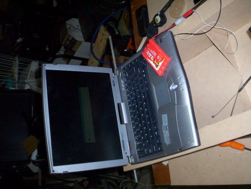 laptop again but closer and yes the rc car battery is powering it!!
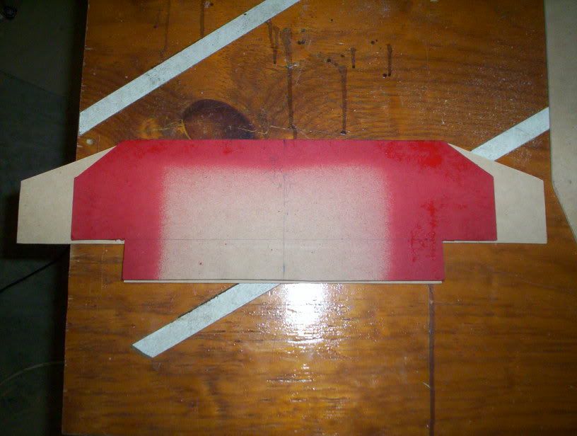 just to show how much I screwed up the red shows the original part
 again showing how much I screwed up. the error occured when moving parts around in turbocad.
 More room inside the upper hull.
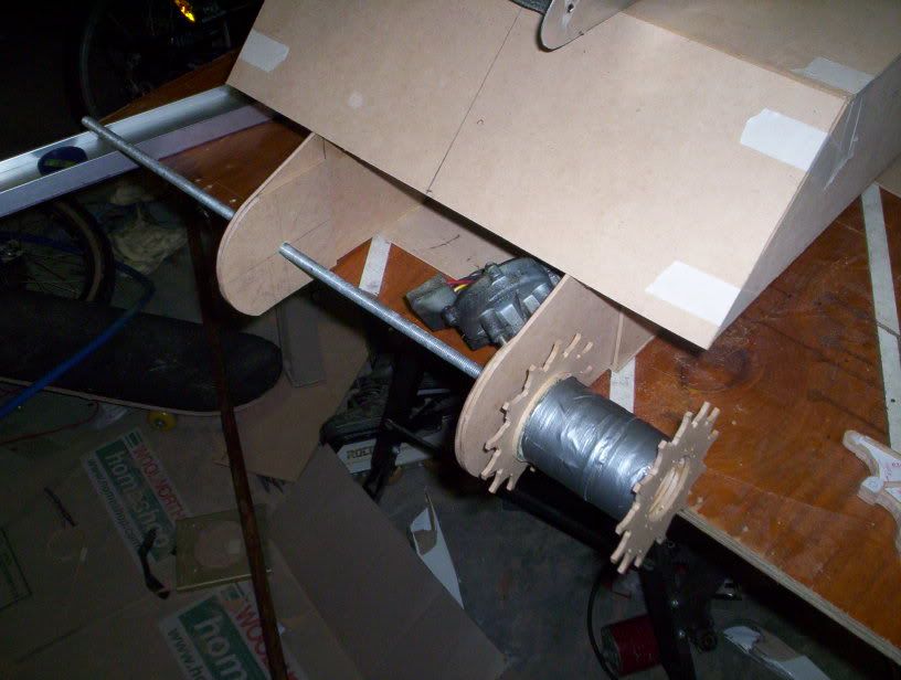 the front showing the repaired sprocket hub (mdf isnt that strong)
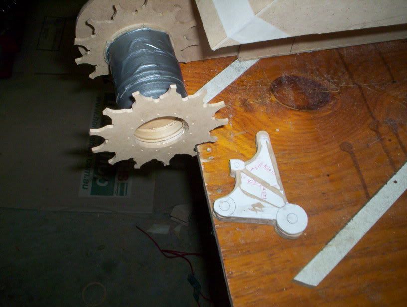 showing one of the suspension arms next to the sprocket
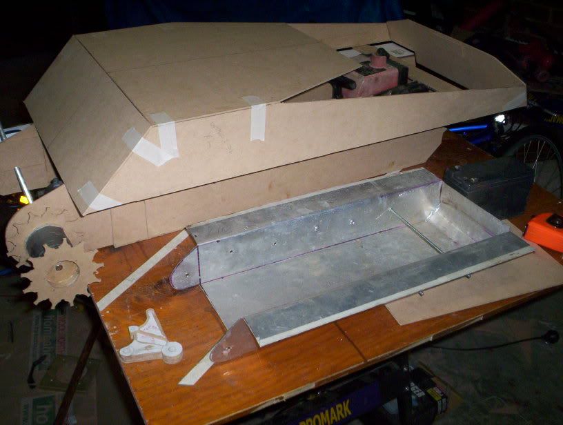 Just to show the difference between the 1:10 hull I created (Couldnt fit my wiper motors in it) and 1:6 hull
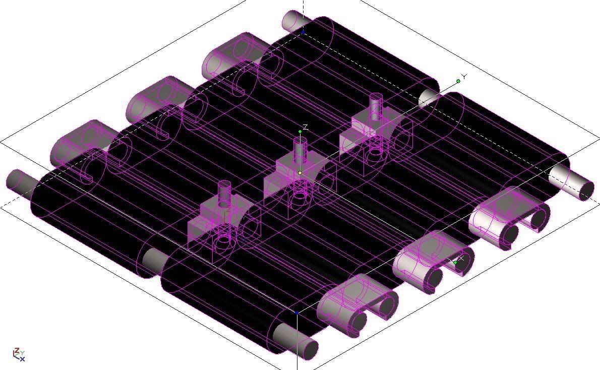 Picture of the CAD track link
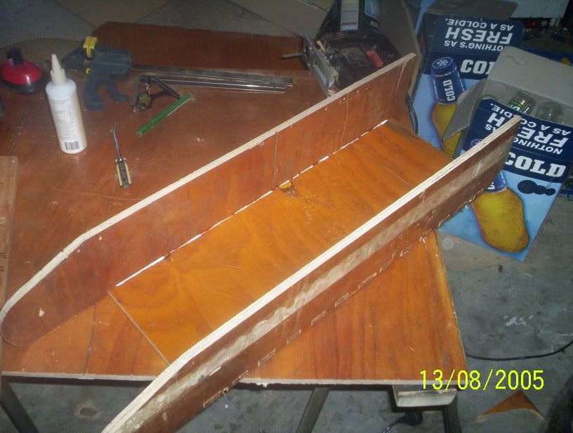 Hull floor and sides fitted
 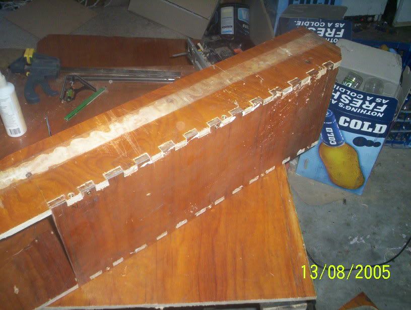 Showing hull floor and sides joined using finger joints, Next time will use router not jigsaw
  Showing sponson sides fitted, two wiper motors sited and one H bridge speed controller.
 the pictures are as follows:
 Showing one wheel fitted and pivot points
 This one shows the cad image glued to ply
 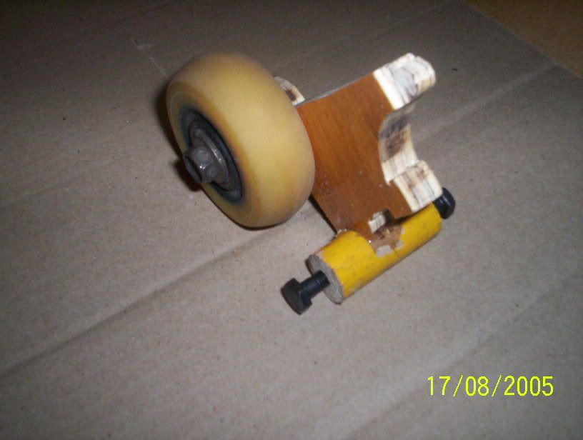 Another shot of pivot and wheel
 the pictures are as follows: