

Contents
Remote Access Over the Internet
Connecting Networks Over the Internet
2.2 Tunneling Protocols and the Basic Tunneling Requirements
Phase 1: PPP Link Establishment
Phase 4: Invoking Network Layer Protocol(s)
Point-to-Point Tunneling Protocol (PPTP)
Layer Two Tunneling Protocol (L2TP)
Advantages
of L2TP/IPSec over PPTP
Advantages of PPTP over L2TP/IPSec
Symmetric
vs. Asymmetric Encryption (Private Key vs. Public Key)
Extensible
Authentication Protocol (EAP)
Transport
Level Security (EAP-TLS)
Negotiated
Security Association
Encapsulating
Security Payload
Accounting, Auditing,
and Alarming
Introduction
A
virtual private network (VPN) is the extension of a private network that
encompasses links across shared or public networks like the Internet. A VPN
enables you to send data between two computers across a shared or public
internetwork in a manner that emulates the properties of a point-to-point
private link. The act of configuring and creating a virtual private network is
known as virtual private networking.
To emulate a
point-to-point link, data is encapsulated, or wrapped, with a header that
provides routing information allowing it to traverse the shared or public
transit internetwork to reach its endpoint. To emulate a private link, the data
being sent is encrypted for confidentiality. Packets that are intercepted on the
shared or public network are indecipherable without the encryption keys. The
portion of the connection in which the private data is encapsulated is known as
the tunnel. The portion of the connection in which the private data is encrypted
is known as the virtual private
network (VPN) connection.
Figure 1:
Virtual private network connection
VPN
connections allow users working at home or on the road to connect in a secure
fashion to a remote corporate server using the routing infrastructure provided
by a public internetwork (such as the Internet). From the user’s perspective,
the VPN connection is a point-to-point connection between the user’s computer
and a corporate server. The nature of the intermediate internetwork is
irrelevant to the user because it appears as if the data is being sent over a
dedicated private link.
VPN technology
also allows a corporation to connect to branch offices or to other companies
over a public internetwork (such as the Internet), while maintaining secure
communications. The VPN connection across the Internet logically operates as a
wide area network (WAN) link between the sites.
In both of
these cases, the secure connection across the internetwork appears to the user
as a private network communication—despite the fact that this communication
occurs over a public internetwork—hence the name virtual
private network.
VPN technology
is designed to address issues surrounding the current business trend toward
increased telecommuting and widely distributed global operations, where workers
must be able to connect to central resources and must be able to communicate
with each other.
To provide
employees with the ability to connect to corporate computing resources,
regardless of their location, a corporation must deploy a scalable remote access
solution. Typically, corporations choose either an MIS department solution,
where an internal information systems department is charged with buying,
installing, and maintaining corporate modem pools and a private network
infrastructure; or they choose a value-added network (VAN) solution, where they
pay an outsourced company to buy, install, and maintain modem pools and a
telecommunication infrastructure.
Neither of these solutions provides the necessary scalability, in terms of cost, flexible administration, and demand for connections. Therefore, it makes sense to replace the modem pools and private network infrastructure with a less expensive solution based on Internet technology so that the business can focus on its core competencies. With an Internet solution, a few Internet connections through Internet service providers (ISPs) and VPN server computers can serve the remote networking needs of hundreds or thousands of remote clients and branch offices.
The
next few subsections describe the more common VPN configurations in more detail.
VPNs
provide remote access to corporate resources over the public Internet, while
maintaining privacy of information. Figure 2 shows a VPN connection used to
connect a remote user to a corporate intranet.
Figure
2: Using a VPN connection to connect a remote client to a private intranet
Rather
than making a long distance (or 1-800) call to a corporate or outsourced network
access server (NAS), the user calls a local ISP. Using the connection to the
local ISP, the VPN software creates a virtual private network between the
dial-up user and the corporate VPN server across the Internet.
There
are two methods for using VPNs to connect local area networks at remote sites:
·
Using
dedicated lines to connect a branch office to a corporate LAN.
Rather than using an expensive long-haul dedicated circuit between the branch
office and the corporate hub, both the branch office and the corporate hub
routers can use a local dedicated circuit and local ISP to connect to the
Internet. The VPN software uses the local ISP connections and the Internet to
create a virtual private network between the branch office router and corporate
hub router.
·
Using
a dial-up line to connect a branch office to a corporate LAN.
Rather than having a router at the branch office make a long distance (or 1-800)
call to a corporate or outsourced NAS, the router at the branch office can call
the local ISP. The VPN software uses the connection to the local ISP to create a
VPN between the branch office router and the corporate hub router across the
Internet.
Figure
3: Using a VPN connection to connect two remote sites
In
both cases, the facilities that connect the branch office and corporate offices
to the Internet are local. The corporate hub router that acts as a VPN server
must be connected to a local ISP with a dedicated line. This VPN server must be
listening 24 hours a day for incoming VPN traffic.
In
some corporate internetworks, the departmental data is so sensitive that the
department’s LAN is physically disconnected from the rest of the corporate
internetwork. Although this protects the department’s confidential
information, it creates information accessibility problems for those users not
physically connected to the separate LAN.
Figure
4: Using a VPN connection to connect to a secured or hidden network
VPNs allow the department’s LAN to be physically connected to the corporate internetwork but separated by a VPN server. The VPN server is not acting as a router between the corporate internetwork and the department LAN. A router would connect the two networks, allowing everyone access to the sensitive LAN. By using a VPN, the network administrator can ensure that only those users on the corporate internetwork who have appropriate credentials (based on a need-to-know policy within the company) can establish a VPN with the VPN server and gain access to the protected resources of the department. Additionally, all communication across the VPN can be encrypted for data confidentiality. Those users who do not have the proper credentials cannot view the department LAN.
Typically,
when deploying a remote networking solution, an enterprise needs to facilitate
controlled access to corporate resources and information. The solution must
allow roaming or remote clients to connect to LAN resources, and the solution
must allow remote offices to connect to each other to share resources and
information (router-to-router connections). In addition, the solution must
ensure the privacy and integrity of data as it traverses the Internet. The same
concerns apply in the case of sensitive data traversing a corporate internetwork.
Therefore,
a VPN solution should provide at least all of the following:
·
User
Authentication. The solution must
verify the VPN client’s identity and restrict VPN access to authorized users
only. It must also provide audit and accounting records to show who accessed
what information and when.
·
Address
Management. The solution must assign
a VPN client’s address on the intranet and ensure that private addresses are
kept private.
·
Data
Encryption. Data carried on the
public network must be rendered unreadable to unauthorized clients on the
network.
·
Key
Management. The solution must
generate and refresh encryption keys for the client and the server.
·
Multiprotocol
Support. The solution must handle
common protocols used in the public network. These include IP, Internetwork
Packet Exchange (IPX), and so on.
An Internet VPN solution based on the Point-to-Point Tunneling Protocol (PPTP) or Layer Two Tunneling Protocol (L2TP) meets all of these basic requirements and takes advantage of the broad availability of the Internet. Other solutions, including Internet Protocol Security (IPSec), meet only some of these requirements, but remain useful for specific situations.
VPNs promise two main advantages over competing approaches -- cost savings, and scalability (that is really just a different form of cost savings).
One way a VPN lowers costs is by eliminating the need for expensive long-distance leased lines. With VPNs, an organization needs only a relatively short dedicated connection to the service provider. This connection could be a local leased line (much less expensive than a long-distance one), or it could be a local broadband connection such as DSL service.
Another way VPNs reduce costs is by lessening the need for long-distance telephone charges for remote access. Recall that to provide remote access service, VPN clients need only call into the nearest service provider's access point. In some cases this may require a long distance call, but in many cases a local call will suffice.
A third, more subtle way that VPNs may lower costs is through offloading of the support burden. With VPNs, the service provider rather than the organization must support dial-up access, for example. Service providers can in theory charge much less for their support than it costs a company internally because the public provider's cost is shared amongst potentially thousands of customers.
The cost to an organization of traditional leased lines may be reasonable at first but can increase exponentially as the organization grows. A company with two branch offices, for example, can deploy just one dedicated line to connect the two locations. If a third branch office needs to come online, just two additional lines will be required to directly connect that location to the other two.
However, as an organization grows and more companies must be added to the network, the number of leased lines required increases dramatically. Four branch offices require six lines for full connectivity, five offices require ten lines, and so on. Mathematicans call this phenomenon a "combinatorial explosion," and in a traditional WAN this explosion limits the flexibility for growth. VPNs that utilize the Internet avoid this problem by simply tapping into the geographically-distributed access already available.
Compared to leased lines, Internet-based VPNs offer greater global reach, given that Internet access points are accessible in many places where dedicated lines are not available.
With the hype that has surrounded VPNs historically, the potential pitfalls or "weak spots" in the VPN model can be easy to forget. These four concerns with VPN solutions are often raised.
1.
VPNs require an in-depth understanding of public network security issues and
taking proper precautions in VPN deployment.
2. The availability and performance of an organization's wide-area VPN (over the
Internet in particular) depends on factors largely outside of their control.
3. VPN technologies from different vendors may not work well together due to
immature standards.
4. VPNs need to accomodate protocols other than IP and existing
("legacy") internal network technology.
TUNNELING
Basics
Tunneling
is a method of using an internetwork infrastructure to transfer data for one
network over another network. The data to be transferred (or payload)
can be the frames (or packets) of another protocol. Instead of sending a frame
as it is produced by the originating node, the tunneling protocol encapsulates
the frame in an additional header. The additional header provides routing
information so that the encapsulated payload can traverse the intermediate
internetwork.
The
encapsulated packets are then routed between tunnel endpoints over the
internetwork. The logical path through which the encapsulated packets travel
through the internetwork is called a tunnel.
Once the encapsulated frames reach their destination on the internetwork, the
frame is decapsulated and forwarded to its final destination. Tunneling includes
this entire process (encapsulation, transmission, and decapsulation of packets).
Figure
5: Tunneling
The
transit internetwork can be any internetwork—the Internet is a public
internetwork and is the most widely known real world example. There are many
examples of tunnels that are carried over corporate internetworks. And while the
Internet provides one of the most pervasive and cost-effective internetworks,
references to the Internet in this paper can be replaced by any other public or
private internetwork that acts as a transit internetwork.
Tunneling
technologies have been in existence for some time. Some examples of mature
technologies include:
·
SNA
tunneling over IP internetworks. When
System Network Architecture (SNA) traffic is sent across a corporate IP
internetwork, the SNA frame is encapsulated in a UDP and IP header.
·
IPX
tunneling for Novell NetWare over IP internetworks.
When
an IPX packet is sent to a NetWare server or IPX router, the server or the
router wraps the IPX packet in a UDP and IP header, and then sends it across an
IP internetwork. The destination IP-to-IPX router removes the UDP and IP header
and forwards the packet to the IPX destination.
New
tunneling technologies have been introduced in recent years. These newer
technologies—which are the primary focus of this paper—include:
·
Point-to-Point
Tunneling Protocol (PPTP).
PPTP allows IP, IPX, or NetBEUI traffic to be encrypted, and then encapsulated
in an IP header to be sent across a corporate IP internetwork or a public IP
internetwork such as the Internet.
·
Layer
Two Tunneling Protocol (L2TP). L2TP
allows IP, IPX, or NetBEUI traffic to be encrypted, and then sent over any
medium that supports point-to-point datagram delivery, such as IP, X.25, Frame
Relay, or ATM.
· IPSec tunnel mode. IPSec tunnel mode allows IP packets to be encrypted, and then encapsulated in an IP header to be sent across a corporate IP internetwork or a public IP internetwork such as the Internet.
For
Layer 2 tunneling technologies, such as PPTP and L2TP, a tunnel is similar to a
session; both of the tunnel endpoints must agree to the tunnel and must
negotiate configuration variables, such as address assignment or encryption or
compression parameters. In most cases, data transferred across the tunnel is
sent using a datagram-based protocol. A tunnel maintenance protocol is used as
the mechanism to manage the tunnel.
Layer
3 tunneling technologies generally assume that all of the configuration issues
are preconfigured, often by manual processes. For these protocols, there may be
no tunnel maintenance phase. For Layer 2 protocols (PPTP and L2TP), however, a
tunnel must be created, maintained, and then terminated.
Once the tunnel is established, tunneled data can be sent. The tunnel client or server uses a tunnel data transfer protocol to prepare the data for transfer. For example, when the tunnel client sends a payload to the tunnel server, the tunnel client first appends a tunnel data transfer protocol header to the payload. The client then sends the resulting encapsulated payload across the internetwork, which routes it to the tunnel server. The tunnel server accepts the packets, removes the tunnel data transfer protocol header, and forwards the payload to the target network. Information sent between the tunnel server and the tunnel client behaves similarly.
Because
they are based on the well-defined PPP protocol, Layer 2 protocols (such as PPTP
and L2TP) inherit a suite of useful features. These features, and their Layer 3
counterparts address the basic VPN requirements, as outlined below.
·
User
Authentication. Layer 2 tunneling
protocols inherit the user authentication schemes of PPP, including the EAP
methods discussed below. Many Layer 3 tunneling schemes assume that the
endpoints were well known (and authenticated) before the tunnel was established.
An exception to this is IPSec Internet Key Exchange (IKE) negotiation, which
provides mutual authentication of the tunnel endpoints. Most IPSec
implementations including Windows 2000 support computer-based certificates only,
rather than user certificates. As a result, any user with access to one of the
endpoint computers can use the tunnel. This potential security weakness can be
eliminated when IPSec is paired with a Layer 2 protocol such as L2TP.
Token
card support. Using the Extensible Authentication Protocol (EAP), Layer 2
tunneling protocols can support a wide variety of authentication methods,
including one-time passwords, cryptographic calculators, and smart cards. Layer
3 tunneling protocols can use similar methods; for example, IPSec defines public
key certificate authentication in its IKE negotiation.
·
Dynamic
address assignment.
Layer 2 tunneling supports dynamic
assignment of client addresses based on the Network Control Protocol (NCP)
negotiation mechanism. Generally, Layer 3 tunneling schemes assume that an
address has already been assigned prior to initiation of the tunnel. Schemes for
assignment of addresses in IPSec tunnel mode are currently under development and
are not yet available.
·
Data
compression. Layer 2 tunneling
protocols support PPP-based compression schemes. For example, the Microsoft
implementations of both PPTP and L2TP use Microsoft Point-to-Point Compression (MPPC).
The IETF is investigating similar mechanisms (such as IP Compression) for the
Layer 3 tunneling protocols.
·
Data
encryption. Layer 2 tunneling
protocols support PPP-based data encryption mechanisms. The Microsoft
implementation of PPTP supports optional use of Microsoft Point-to-Point
Encryption (MPPE), based on the RSA/RC4 algorithm. Layer 3 tunneling protocols
can use similar methods; for example, IPSec defines several optional data
encryption methods, which are negotiated during the IKE exchange. The Microsoft
implementation of the L2TP protocol uses IPSec encryption to protect the data
stream from the VPN client to the VPN server.
·
Key
Management. MPPE, a Layer 2
encryption mechanism, relies on the initial key generated during user
authentication, and then refreshes it periodically. IPSec explicitly negotiates
a common key during the IKE exchange, and also refreshes it periodically.
· Multiprotocol support. Layer 2 tunneling supports multiple payload protocols, which makes it easy for tunneling clients to access their corporate networks using IP, IPX, NetBEUI, and so on. In contrast, Layer 3 tunneling protocols, such as IPSec tunnel mode, typically support only target networks that use the IP protocol.
Because
the Layer 2 protocols depend heavily on the features originally specified for
PPP, it is worth examining this protocol more closely. PPP was designed to send
data across dial-up or dedicated point-to-point connections. PPP encapsulates
IP, IPX, and NetBEUI packets within PPP frames, and then transmits the
PPP-encapsulated packets across a point-to-point link. PPP is used between a
dial-up client and an NAS.
There are four distinct phases of negotiation in a PPP dial-up session. Each of these four phases must complete successfully before the PPP connection is ready to transfer user data.
PPP uses Link Control Protocol (LCP) to establish, maintain, and end the physical connection. During the initial LCP phase, basic communication options are selected. During the link establishment phase (Phase 1), authentication protocols are selected, but they are not actually implemented until the connection authentication phase (Phase 2). Similarly, during LCP a decision is made as to whether the two peers will negotiate the use of compression and/or encryption. The actual choice of compression and encryption algorithms and other details occurs during Phase 4.
In
the second phase, the client PC presents the user’s credentials to the remote
access server. A secure authentication scheme provides protection against replay
attacks and remote client impersonation. A replay attack occurs when a third party monitors a successful
connection and uses captured packets to play back the remote client’s response
so that it can gain an authenticated connection. Remote client impersonation occurs when a third party takes over an
authenticated connection. The intruder waits until the connection has been
authenticated, and then traps the conversation parameters, disconnects the
authenticated user, and takes control of the authenticated connection.
Most
implementations of PPP provide limited authentication methods, typically
Password Authentication Protocol (PAP), Challenge Handshake Authentication
Protocol (CHAP), and Microsoft Challenge Handshake Authentication Protocol
(MS-CHAP).
·
Password
Authentication Protocol (PAP).
PAP is a simple, clear-text authentication scheme. The NAS requests the user
name and password, and PAP returns them in clear text (unencrypted). Obviously,
this authentication scheme is not secure because a third party could capture the
user’s name and password and use it to get subsequent access to the NAS and
all of the resources provided by the NAS. PAP provides no protection against
replay attacks or remote client impersonation once the user’s password is
compromised.
·
Challenge-Handshake
Authentication Protocol (CHAP).
CHAP is an encrypted authentication mechanism that avoids transmission of the
actual password on the connection. The NAS sends a challenge, which consists of
a session ID and an arbitrary challenge string, to the remote client. The
remote client must use the MD5 one-way hashing algorithm to return the user name
and an encryption of the challenge, session ID, and the client’s password. The
user name is sent unhashed.
CHAP
is an improvement over PAP because the clear-text password is not sent over the
link. Instead, the password is used to create an encrypted hash from the
original challenge. The server knows the client’s clear-text password and can,
therefore, replicate the operation and compare the result to the password sent
in the client’s response. CHAP protects against replay attacks by using an
arbitrary challenge string for each authentication attempt. CHAP protects
against remote client impersonation by unpredictably sending repeated challenges
to the remote client throughout the duration of the connection.
·
Microsoft
Challenge-Handshake Authentication Protocol (MS-CHAP).
MS-CHAP is an encrypted authentication mechanism very similar to CHAP. As in
CHAP, the NAS sends a challenge, which consists of a session ID and an arbitrary
challenge string, to the remote client. The remote client must return the user
name and an encrypted form of the challenge string, the session ID, and the
MD4-hashed password. This design, which uses a hash of the MD4 hash of the
password, provides an additional level of security because it allows the server
to store hashed passwords instead of clear-text passwords. MS-CHAP also provides
additional error codes, including a password expired code, and additional
encrypted client-server messages that permit users to change their passwords. In
MS-CHAP, both the access client and the NAS independently generate an initial
key for subsequent data encryption by MPPE. Therefore, MS-CHAP authentication is
required to enable MPPE-based data encryption.
·
MS-CHAP
version 2 (MS-CHAP v2).
MS-CHAP v2 is an updated encrypted authentication mechanism that provides
stronger security for the exchange of user name and password credentials and
determination of encryption keys. With MS-CHAP v2, the NAS sends a challenge to
the access client that consists of a session identifier and an arbitrary
challenge string. The remote access client sends a response that contains the
user name, an arbitrary peer challenge string, and an encrypted form of the
received challenge string, the peer challenge string, the session identifier,
and the user's password. The NAS checks the response from the client and sends
back a response containing an indication of the success or failure of the
connection attempt and an authenticated response based on the sent challenge
string, the peer challenge string, the encrypted response of the client, and the
user's password. The remote access client verifies the authentication response
and, if correct, uses the connection. If the authentication response is not
correct, the remote access client terminates the connection.
Using
this process, MS-CHAP v2 provides mutual authentication¾the
NAS verifies that the access client has knowledge of the user's password and the
access client verifies that the NAS has knowledge of the user's password.
MS-CHAP v2 also determines two encryption keys, one for data sent and one for
data received.
During
phase 2 of PPP link configuration, the NAS collects the authentication data, and
then validates the data against its own user database or a central
authentication database server, such as one maintained by a Windows domain
controller, or the authentication data is sent to a Remote Authentication
Dial-in User Service (RADIUS) server.
The
Microsoft implementation of PPP includes an optional callback control phase.
This phase uses the Callback Control Protocol (CBCP) immediately after the
authentication phase. If configured for callback, both the remote client and NAS
disconnect after authentication. The NAS then calls the remote client back at a
specified phone number. This provides an additional level of security to dial-up
networking. The NAS allows connections from remote clients physically residing
at specific phone numbers only.
Once
the previous phases have been completed, PPP invokes the various network control
protocols (NCPs) that were selected during the link establishment phase (Phase
1) to configure protocols used by the remote client. For example, during this
phase the IP control protocol (IPCP) can assign a dynamic address to the dial-in
user. In the Microsoft implementation of PPP, the compression control protocol
is used to negotiate both data compression (using MPPC) and data encryption
(using MPPE) for because both are implemented in the same routine.
Once
the four phases of negotiation have been completed, PPP begins to forward data
to and from the two peers. Each transmitted data packet is wrapped in a
PPP header which is removed by the receiving system. If data compression was
selected in phase 1 and negotiated in phase 4, data is compressed before
transmission. If data encryption is selected and negotiated, data is encrypted
before transmission.
PPTP
is a Layer 2 protocol that encapsulates PPP frames in IP datagrams for
transmission over an IP internetwork, such as the Internet. PPTP can be used for
remote access and router-to-router VPN connections. PPTP is documented in RFC
2637.
The
Point-to-Point Tunneling Protocol (PPTP) uses a TCP connection for tunnel
maintenance and a modified version of Generic Routing Encapsulation (GRE) to
encapsulate PPP frames for tunneled data. The payloads of the encapsulated PPP
frames can be encrypted and/or compressed. Figure 6 shows the structure of a
PPTP packet containing user data.

Figure 6. Structure of a PPTP packet containing user data
L2TP
is a combination of PPTP and Layer 2 Forwarding (L2F), a technology proposed by
Cisco Systems, Inc. L2TP represents the best features of PPTP and L2F. L2TP
encapsulates PPP frames to be sent over IP, X.25, Frame Relay, or Asynchronous
Transfer Mode (ATM) networks. When configured to use IP as its datagram
transport, L2TP can be used as a tunneling protocol over the Internet. L2TP is
documented in RFC 2661.
L2TP
over IP internetworks uses UDP and a series of L2TP messages for tunnel
maintenance. L2TP also uses UDP to send L2TP-encapsulated PPP frames as the
tunneled data. The payloads of encapsulated PPP frames can be encrypted and/or
compressed. Figure 7 shows the structure of an L2TP packet containing user data.
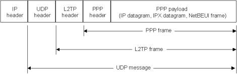
Figure
7. Structure of an L2TP packet containing user data
In
Windows 2000, IPSec Encapsulating Security Payload (ESP) is used to encrypt the
L2TP packet. This is known as L2TP/IPSec. The result after applying ESP is shown
in Figure 8.
Figure 8. Encryption of an L2TP packet with IPSec ESP
Both
PPTP and L2TP/IPSec use PPP to provide an initial envelope for the data, and
then append additional headers for transport through the internetwork. However,
there are the following differences:
·
With PPTP, data encryption begins
after the PPP connection process (and, therefore, PPP authentication) is
completed. With L2TP/IPSec, data encryption begins before the PPP connection
process by negotiating an IPSec security association.
·
PPTP connections use MPPE, a
stream cipher that is based on the Rivest-Shamir-Aldeman (RSA) RC-4 encryption
algorithm and uses 40, 56, or 128-bit encryption keys. Stream ciphers encrypt
data as a bit stream. L2TP/IPSec connections use the Data Encryption Standard
(DES), which is a block cipher that uses either a 56-bit key for DES or three
56-bit keys for 3-DES. Block ciphers encrypt data in discrete blocks (64-bit
blocks, in the case of DES).
· PPTP connections require only user-level authentication through a PPP-based authentication protocol. L2TP/IPSec connections require the same user-level authentication and, in addition, computer-level authentication using computer certificates.
The
following are the advantages of using L2TP/IPSec over PPTP in Windows 2000:
·
IPSec provides per packet data
authentication (proof that the data was sent by the authorized user), data
integrity (proof that the data was not modified in transit), replay protection
(prevention from resending a stream of captured packets), and data
confidentiality (prevention from interpreting captured packets without the
encryption key). By contrast, PPTP provides only per-packet data
confidentiality.
·
L2TP/IPSec connections provide
stronger authentication by requiring both computer-level authentication through
certificates and user-level authentication through a PPP authentication
protocol.
· PPP packets exchanged during user-level authentication are never sent in an unencrypted form because the PPP connection process for L2TP/IPSec occurs after the IPSec security associations (SAs) are established. If intercepted, the PPP authentication exchange for some types of PPP authentication protocols can be used to perform offline dictionary attacks and determine user passwords. By encrypting the PPP authentication exchange, offline dictionary attacks are only possible after the encrypted packets have been successfully decrypted.
The
following are advantages of PPTP over L2TP/IPSec in Windows 2000:
·
PPTP does not require a
certificate infrastructure. L2TP/IPSec requires a certificate infrastructure for
issuing computer certificates to the VPN server computer (or other
authenticating server) and all VPN client computers.
·
PPTP can be used by computers
running Windows XP, Windows 2000, Windows NT version 4.0, Windows Millennium
Edition (ME), Windows 98, and Windows 95 with the Windows Dial-Up Networking 1.3
Performance & Security Update. L2TP/IPSec can only be used with Windows XP
and Windows 2000 VPN clients. Only these clients support the L2TP
protocol, IPSec, and the use of certificates.
· PPTP clients and server can be placed behind a network address translator (NAT) if the NAT has the appropriate editors for PPTP traffic. L2TP/IPSec-based VPN clients or servers cannot be placed behind a NATunless both support IPSec NAT Traversal (NAT-T). IPSec NAT-T is supported by Windows Server 2003, Microsoft L2TP/IPSec VPN Client, and for VPN clients with L2TP/IPSec NAT-T Update for Windows XP and Windows 2000.
IPSec
is a Layer 3 protocol standard that supports the secured transfer of information
across an IP internetwork. IPSec is more fully described in the Advanced
Security section below. However,
one aspect of IPSec should be discussed in the context of tunneling protocols.
In addition to its definition of encryption mechanisms for IP traffic, IPSec
defines the packet format for an IP over IP tunnel mode, generally referred to
as IPSec tunnel mode. An IPSec tunnel
consists of a tunnel client and a tunnel server, which are both configured to
use IPSec tunneling and a negotiated encryption mechanism.
IPSec
tunnel mode uses the negotiated security method (if any) to encapsulate and
encrypt entire IP packets for secure transfer across a private or public IP
internetwork. The encrypted payload is then encapsulated again with a plain-text
IP header and sent on the internetwork for delivery to the tunnel server. Upon
receipt of this datagram, the tunnel server processes and discards the
plain-text IP header, and then decrypts its
contents to retrieve the original payload IP packet. The payload IP packet is
then processed normally and routed to its destination on the target network.
IPSec
tunnel mode has the following features and limitations:
·
It supports IP traffic only.
·
It functions at the bottom of the
IP stack; therefore, applications and higher-level protocols inherit its
behavior.
· It is controlled by a security policy—a set of filter-matching rules. This security policy establishes the encryption and tunneling mechanisms available, in order of preference, and the authentication methods available, also in order of preference. As soon as there is traffic, the two computers perform mutual authentication, and then negotiate the encryption methods to be used. Thereafter, all traffic is encrypted using the negotiated encryption mechanism, and then wrapped in a tunnel header.
Tunnels
can be created in various ways.
·
Voluntary
tunnels: A user or client computer
can issue a VPN request to configure and create a voluntary tunnel. In this
case, the user’s computer is a tunnel endpoint and acts as the tunnel client.
·
Compulsory
tunnels: A VPN-capable dial-up access
server configures and creates a compulsory tunnel. With a compulsory tunnel, the
user’s computer is not a tunnel endpoint. Another device, the dial-up access
server, between the user’s computer and the tunnel server is the tunnel
endpoint and acts as the tunnel client.
To date, voluntary tunnels are proving to be the more popular type of tunnel. The following sections describe each of these tunnel types in greater detail.
Voluntary
tunneling occurs when a workstation or routing server uses tunneling client
software to create a virtual connection to the target tunnel server. To
accomplish this, the appropriate tunneling protocol must be installed on the
client computer. For the protocols discussed in this paper, voluntary tunnels
require an IP connection (either LAN or dial-up).
In
a dial-up situation, the client must establish a dial-up connection
to the internetwork before the client can set up a tunnel. This is the
most common case. The best example of this is the dial-up Internet user, who
must dial an ISP and obtain an Internet connection before a tunnel over the
Internet can be created.
For
a LAN-attached computer, the client already has a connection to the internetwork
that can provide routing of encapsulated payloads to the chosen LAN tunnel
server. This would be the case for a client on a corporate LAN that initiates a
tunnel to reach a private or hidden subnet on that LAN (such as the Human
Resources network discussed previously).
It is a common misconception that VPN connections require a dial-up connection. They require only IP connectivity between the VPN client and VPN server. Some clients (such as home computers) use dial-up connections to the Internet to establish IP transport. This is a preliminary step in preparation for creating a tunnel and is not part of the tunnel protocol itself.
A
number of vendors that sell dial-up access servers have implemented the ability
to create a tunnel on behalf of a dial-up client. The computer or network device
providing the tunnel for the client computer is variously known as a Front End
Processor (FEP) in PPTP, an L2TP Access Concentrator (LAC) in L2TP, or an IP
Security Gateway in IPSec. For the purposes of this white paper, the term FEP is
used to describe this functionality, regardless of the tunneling protocol. To
carry out its function, the FEP must have the appropriate tunneling protocol
installed and must be capable of establishing the tunnel when the client
computer connects.
In
the Internet example, the client computer places a dial-up call to a
tunneling-enabled NAS at the ISP. For example, a corporation may have contracted
with an ISP to deploy a nationwide set of FEPs. These FEPs can establish tunnels
across the Internet to a tunnel server connected to the corporation’s private
network, thus consolidating calls from geographically diverse locations into a
single Internet connection at the corporate network.
This
configuration is known as compulsory tunneling because the client is compelled
to use the tunnel created by the FEP. Once the initial connection is made, all
network traffic to and from the client is automatically sent through the tunnel.
With compulsory tunneling, the client computer makes a single PPP connection.
When a client dials into the NAS, a tunnel is created and all traffic is
automatically routed through the tunnel. An FEP can be configured to tunnel all
dial-up clients to a specific tunnel server. The FEP could also tunnel
individual clients, based on the user name or destination.
Unlike
the separate tunnels created for each voluntary client, a tunnel between the FEP
and the tunnel server can be shared by multiple dial-up clients. When a second
client dials into the access server (FEP) to reach a destination for which a
tunnel already exists, there is no need to create a new instance of the tunnel
between the FEP and tunnel server. Instead, the data traffic for the new client
is carried over the existing tunnel. Since there can be multiple clients in a
single tunnel, the tunnel is not terminated until the last user of the tunnel
disconnects.
Advanced
SECURITY
Features
Because
the Internet facilitates the creation of VPNs from anywhere, networks need
strong security features to prevent unwelcome access to private networks and to
protect private data as it traverses the public network. User authentication and
data encryption have already been discussed. This section provides a brief look
ahead to the stronger authentication and encryption capabilities that are
available with EAP and IPSec.
Symmetric,
or private-key, encryption (also known as conventional encryption) is based on a
secret key that is shared by both communicating parties. The sending party uses
the secret key as part of the mathematical operation to encrypt (or encipher)
plain text to cipher text. The receiving party uses the same secret key to
decrypt (or decipher) the cipher text to plain text. Examples of symmetric
encryption schemes are the RSA RC4 algorithm (which provides the basis for
Microsoft Point-to-Point Encryption (MPPE), Data Encryption Standard (DES), the
International Data Encryption Algorithm (IDEA), and the Skipjack encryption
technology proposed by the United States government (and implemented in the
Clipper chip).
Asymmetric,
or public-key, encryption uses two different keys for each user: one is a
private key known only to this one user; the other is a corresponding public
key, which is accessible to anyone. The private and public keys are
mathematically related by the encryption algorithm. One key is used for
encryption and the other for decryption, depending on the nature of the
communication service being implemented.
In
addition, public key encryption technologies allow digital signatures to be
placed on messages. A digital signature uses the sender’s private key to
encrypt some portion of the message. When the message is received, the receiver
uses the sender’s public key to decipher the digital signature to verify the
sender’s identity.
With
symmetric encryption, both sender and receiver have a shared secret key. The
distribution of the secret key must occur (with adequate protection) prior to
any encrypted communication. However, with asymmetric encryption, the sender
uses a private key to encrypt or digitally sign messages, while the receiver
uses a public key to decipher these messages. The public key can be freely
distributed to anyone who needs to receive the encrypted or digitally
signed messages. The sender needs to carefully protect the private key only.
To
secure the integrity of the public key, the public key is published with a certificate.
A certificate (or public key
certificate) is a data structure that is digitally signed by a certification
authority (CA)—an authority that users of the certificate can trust. The
certificate contains a series of values, such as the certificate name and usage,
information identifying the owner of the public key, the public key itself, an
expiration date, and the name of the certificate authority. The CA uses its
private key to sign the certificate. If the receiver knows the public key of the
certificate authority, the receiver can verify that the certificate is indeed
from the trusted CA and, therefore, contains reliable information and a valid
public key. Certificates can be distributed electronically (through Web access
or email), on smart cards, or on floppy disks.
In summary, public key certificates provide a convenient, reliable method for verifying the identity of a sender. IPSec can optionally use this method for end-to-end authentication. Remote access servers can use public key certificates for user authentication, as described in the section "Transport Level Security (EAP-TLS)."
As
stated previously, most implementations of PPP provide very limited
authentication methods. EAP is an IETF standard extension to PPP that allows for
arbitrary authentication mechanisms for the validation of a PPP connection. EAP
was designed to allow the dynamic addition of authentication plug-in modules at
both the client and server ends of a connection. This allows vendors to supply a
new authentication scheme at any time. EAP provides the highest flexibility in
authentication uniqueness and variation.
EAP is documented in RFC 2284 and is supported in Microsoft Windows 2000.
EAP-TLS
is an IETF standard (RFC 2716) for a strong authentication method based on
public-key certificates. With EAP-TLS, a client presents a user certificate to
the dial-in server, and the server presents a server certificate to the client.
The first provides strong user authentication to the server; the second provides
assurance that the user has reached the server that he or she expected. Both
systems rely on a chain of trusted authorities to verify the validity of the
offered certificate.
The
user’s certificate could be stored on the dial-up client computer or
stored in an external smart card. In either case, the certificate cannot be
accessed without some form of user identification (PIN number or
name-and-password exchange) between the user and the client computer. This
approach meets the something-you-know-plus-something-you-have criteria
recommended by most security experts.
EAP-TLS is the specific EAP method implemented in Microsoft Windows 2000. Like MS-CHAP and MS-CHAP v2, EAP-TLS returns an encryption key to enable subsequent data encryption by MPPE.
IP
Security (IPSec) was designed by the IETF as an end-to-end mechanism for
ensuring data security in IP-based communications. IPSec has been defined in a
series of RFCs, notably RFCs 2401, 2402, and 2406, which define the overall
architecture, an authentication header to verify data integrity, and an
encapsulation security payload for both data integrity and data encryption.
IPSec
defines two functions that ensure confidentiality: data encryption and data
integrity. As defined by the IETF, IPSec uses an authentication header (AH) to
provide source authentication and integrity without encryption, and the
Encapsulating Security Payload (ESP) to provide authentication and integrity
along with encryption. With IPSec, only the sender and recipient know the
security key. If the authentication data is valid, the recipient knows that the
communication came from the sender and that it was not changed in transit.
IPSec can be envisioned as a layer below the TCP/IP stack. This layer is controlled by a security policy on each computer and a negotiated security association between the sender and receiver. The policy consists of a set of filters and associated security behaviors. If a packet’s IP address, protocol, and port number match a filter, the packet is subject to the associated security behavior.
The
first such packet triggers a negotiation of a security association between the
sender and receiver. Internet Key Exchange (IKE) is the standard protocol for
this negotiation. During an IKE negotiation, the two computers agree on
authentication and data-security methods, perform mutual authentication, and
then generate a shared key for subsequent data encryption.
After
the security association has been established, data transmission can proceed for
each computer, applying data security treatment to the packets that it transmits
to the remote receiver. The treatment can simply ensure the integrity of the
transmitted data, or it can encrypt it as well.
Data
integrity and data authentication for IP payloads can be provided by an
authentication header located between the IP header and the transport header.
The authentication header includes authentication data and a sequence number,
which together are used to verify the sender, ensure that the message has not
been modified in transit, and prevent a replay attack.
The
IPSec authentication header provides no data encryption; clear-text messages can
be sent, and the authentication header ensures that they originated from a
specific user and were not modified in transit.
For
both data confidentiality and protection from third-party capture, ESP provides
a mechanism to encrypt the IP payload. ESP also provides data authentication and
data integrity services; therefore, ESP is an alternative to AH
when data confidentiality is required.
In
selecting a VPN technology, it is important to consider administrative issues.
Large networks need to store per-user directory information in a centralized
data store, or directory service,
so that administrators and applications can add to, modify, or query this
information. Each access or tunnel server could maintain its own internal data
base of per-user properties, such as names, passwords, and dial-in permission
attributes. However, because it is administratively prohibitive to maintain
multiple user accounts on multiple servers and keep them simultaneously current,
most administrators set up a master account database at the directory server or
primary domain controller, or on a RADIUS server.
The
Routing and Remote Access service in Windows 2000 Server is designed to work
with per-user information stored locally or on a domain controller or on a
RADIUS server. Using a domain controller simplifies system administration
because dial-up permissions are a subset of the per-user information that the
administrator is already managing in a single database.
The
Routing and Remote Access service is both a dial-up remote access server and VPN
server for PPTP and L2TP connections. Consequently, these Layer 2 VPN solutions
inherit all of the management infrastructure already in place for dial-up
networking.
In
Windows 2000, the Routing and Remote Access service takes advantage of the
new Active Directory, an enterprise-wide, replicated database based on the
Lightweight Directory Access Protocol (LDAP). LDAP is an industry-standard
protocol for accessing directory services and was developed as a simpler
alternative to the X.500 DAP protocol. LDAP is extensible, vendor-independent,
and standards-based. This integration with the Active Directory allows an
administrator to assign a variety of connection properties for dial-up or VPN
sessions to individual users or groups. These properties can define per-user
filters, required authentication or encryption methods, time-of-day limitations,
and so on.
Redundancy
and load balancing is accomplished using round-robin DNS to split requests among
a number of VPN tunnel servers that share a common security perimeter. A
security perimeter has one external DNS name—for example, microsoft.com—but
several IP addresses, and loads are randomly distributed across all of the IP
addresses. All servers can authenticate access requests against a shared
database, such as a Windows domain controller. Windows domain databases are
replicated between domain controllers.
The
Remote Authentication Dial-in User Service (RADIUS) protocol is a popular method
for managing remote user authentication and authorization. RADIUS is a
lightweight, UDP-based protocol. RADIUS servers can be located anywhere on the
Internet and provide authentication (including PPP PAP, CHAP, MS-CHAP,
MS-CHAP v2, and EAP) and authorization for access servers such as NASes
and VPN servers.
In addition, RADIUS servers can provide a proxy service to forward authentication requests to distant RADIUS servers. For example, many ISPs have joined consortia to allow roaming subscribers to use local services from the nearest ISP for dial-up access to the Internet. These roaming alliances take advantage of the RADIUS proxy service. If an ISP recognizes a user name as being a subscriber to a remote network, the ISP uses a RADIUS proxy to forward the access request to the appropriate network.
To
properly administer a VPN system, network administrators should be able to track
who uses the system, how many connections are made, unusual activity, error
conditions, and situations that may indicate equipment failure. This information
can be used for billing, auditing, and alarm or error-notification purposes.
For
example, an administrator may need to know who connected to the system and for
how long in order to construct billing data. Unusual activity may indicate a
misuse of the system or inadequate system resources. Real-time monitoring of
equipment (for example, unusually high activity on one modem and inactivity on
another) may generate alerts to notify the administrator of a modem failure. The
tunnel server should provide all of this information, and the system should
provide event logs, reports, and a data storage facility to handle the data
appropriately.
The RADIUS protocol defines a suite of call-accounting requests that are independent from the authentication requests discussed above. These messages from the NAS to the RADIUS server request the latter to generate accounting records at the start of a call, the end of a call, and at predetermined intervals during a call. The Routing and Remote Access service can be configured to generate these RADIUS accounting requests separately from connection requests (which could go to the domain controller or to a RADIUS server). This allows an administrator to configure an accounting RADIUS server, whether RADIUS is used for authentication or not. An accounting server can then collect records for every VPN connection for later analysis. A number of third-parties have already written billing and audit packages that read these RADIUS accounting records and produce various useful reports.
VPNs
allow users or corporations to connect to remote servers, branch offices, or to
other companies over a public internetwork, while maintaining secure
communications. In all of these cases, the secure connection appears to the user
as a private network
communication—despite the fact that this communication occurs over a public
internetwork. VPN technology is designed to address issues surrounding the
current business trend toward increased telecommuting and widely distributed
global operations, where workers must be able to connect to central resources
and communicate with each other.
This paper provides an overview of VPN and describes the basic requirements of useful VPN technologies: user authentication, address management, data encryption, key management, and multiprotocol support. It discusses how Layer 2 protocols, specifically PPTP and L2TP, meet these requirements.
