Lesson 10
Chapter 1
IntroductionAt this point, you should be able to visualize a basic network setup. For bus topologies like 10Base2, you have a cable running in a ceiling or along the floor, with each PC connected somewhere along the bus. For star bus or star ring topologies like 10BaseT or Token Ring, in contrast, you have some type of box—hub, MSAU, switch, whatever—with a number of cables leading out, spider-like, to all of the PCs on the network.
On the surface, such a network setup is perfectly viable, but it’s lacking in detail. Certainly, there’s more to real-world networks than this!
This lesson is designed to turn all the conceptual networks we’ve discussed so far into real equipment. You’ll find out what real network hardware— hubs, switches, and so on—looks like and how it is implemented. The little lines you’ve seen used to represent cables will morph into functional wiring systems. Finally, you’ll gain some how-to knowledge of cabling and networking devices.
The Network+ exam requires you to understand the basic concepts of designing a network and installing network cabling, and to recognize the components used in a real network. Network+ does not, however, expect you to be as knowledgeable as a professional network designer or cable installer. If you compare networks to automobiles, the goal of Network+ is not to test your abilities as an auto mechanic, but rather to test whether or not you have a solid understanding of how your automobile works and can talk intelligently to an auto mechanic.
Chapter 2
Cable Basics: It All Starts with a StarLet’s begin by exploring the world of connectivity hardware, starting with the most basic of all networks: a hub, some UTP cable, and a few PCs, in a typical star network.
Fig. 10-01. Hubs and PCsIs the network pictured above a star bus or a star ring? Is it Token Ring, 10BaseT or 100BaseTX? It doesn’t matter! It could be any of these network technologies!
If you have a 10BaseT network, what would you have to do to turn it into a Token Ring network? You only have to replace the 10BaseT NICs in the PCs with Token Ring NICs and replace the 10BaseT hub with a Token Ring MSAU! The cable would stay the same, would it not? As far as the cabling is concerned, there is no difference between these topologies.
Many people find it odd that totally different network technologies like 10BaseT and Token Ring can use the same installed cables. For some reason, people want to think that because the network technology is different, the cabling must also be different. Don’t think that way!
If you went back in time twenty years, pretty much every networking technology had its own type of cabling. Over the years, UTP has edged out other cabling options, making UTP the leading type of cabling today. If an organization already has UTP cabling installed, they’re not going to be too open to a network technology that doesn’t use UTP. Today, if a network technology wants to flourish, it must work with UTP.
Token Ring originally only used STP cable, but it changed to UTP to survive. All new network technologies use UTP—even the new Gigabit Ethernet standards! And virtually all of today’s network technologies use UTP cabling in a star topology.
Only 10Base2 and 10Base5 networks break the pattern of UTP in a star topology, but they are both on the way out. The number of PCs using either of these technologies is tiny compared with the UTP star technologies.
10Base5 is so rare now that it is probably safe to say that it is obsolete—my apologies to the two of you who still use it! 10Base2 still has a good following, but you will never see it in a true permanent installation—in the walls, as network cabling folks say. 10Base2 is still quite popular for temporary networks or for quick and dirty small networks, like a small two-PC office.
Nevertheless, when you want the pretty network with the cable in the walls and the nice outlets, Star topology UTP is the only way to go. The bus technologies do not exist in serious, permanent network installations.
Even though the bus is dead, that does not mean that your older NICs are useless. Almost all older NICS can still connect to UTP. For 10Base5, you can add a transceiver to convert the 9-pin DIX, or AUI, to RJ-45. 10Base2 doesn’t have a transceiver, but most hubs have an extra 10Base2 port, allowing an easy connection. Older STP Token Ring cards have simple converters that plug into the back of the Token Ring NIC, converting to RJ-45.
Fig. 10-02. 10Base 2 connection on hubFiber optic cabling is a partial exception to the UTP/star dominance in network cabling. Fiber optic uses a star topology, but does not use UTP cabling. Fiber optic cabling has properties that UTP just can’t match, and it’s safe in its own special niche. You’ll see how fiber optics are used within the network later in this lesson.
So, with the pure bus topology dead, we’re left with only the star bus or star ring topologies using UTP. The most basic configuration for either of these topologies consists of a hub, or MSAU, with cables running out of it that connect directly to the PCs. Let’s call this the basic star.
The rest of the lesson uses the term hub generically to mean either an Ethernet hub or a Token Ring MSAU. Note also that network techs often use MAU in place of MSAU.
The Basic Star
The basic star topology works great for a diagram, but falls apart spectacularly—as in Figure 10-2 above—when applied to a real-world environment. Four basic problems are at work here.
First, the exposed cables running along the floor are just waiting for someone to trip over them, causing damage to the network and giving that person a wonderful lawsuit opportunity. Even if no accident ever takes place, just the acts of moving and stepping on the cable over time will cause failure.
Second, the thousands of other electrical devices, if allowed to get too close to the cable, create interference that confuses the signals going through the wire.
Third, such a setup limits your ability to make any changes to the network. It is difficult to find out where one cable stops or starts. No one knows which individual cable in the huge pile of cables connected to the hub goes to which user’s machine. Imagine the nightmare of trying to troubleshoot these cables!
Fourth, the only way to upgrade this network is to yank out all of the cables and replace them. Don’t forget that while separate network technologies use UTP, there are subtle variances that, if not addressed through some type of standardized cabling, will prevent you from upgrading the network.
The easiest example is the number of wires used. Let’s say you strung a 10BaseT network. 10BaseT only uses 2 pairs of wires, so you bought UTP cable with two pairs and installed the network. Now you want to upgrade to 100BaseT4. Well, you can forget it—100BaseT4 needs 4 pairs of wires, not 2. Throw the cable out and start over!
There must be a better way to install a physical basic star network. A new installation method must provide safety, protecting the star from vacuum cleaners, clumsy coworkers, and electrical interference. The basic star needs extra hardware to allow for tight organization, so that making changes to the network becomes trivial. Last, the successful star network must have a cabling standard that provides both growing room for the network and the flexibility to upgrade to the next great network technology, whatever it may be.
The people who most wanted these standards were the folks who installed cable for a living. The first network cabling installers were all telephone people. Some very smart telephone installer who was forced into installing network UTP had this phenomenal idea. Telephone systems have outlets at each place where you want a telephone. All of the phone cables are run in the walls to a central location. Phone systems also use a basic star!
If telephone systems use UTP in a basic star and network cabling uses UTP in a basic star, why doesn’t someone come up with some groovy standard for UTP that would allow the same cabling to be used for both telephones and networks? That way you could install only one set of cables, significantly reducing the cost of adding cabling to a building. Of course, this standard would have to address the limitations for both network and telephone cable quality, distances, and distribution. Why do the same thing twice?
Structured Cabling to the Rescue!
The demand for a safe, dependable, and organized network motivated the Electronics Industry Association and the Telephone Industry Association—better known as EIA/TIA—to develop a series of standards that have become the de facto standards used by everyone in the network installation business.
EIA/TIA has developed many standards, but the EIA/TIA 568 standard is considered the centerpiece of all the EIA/TIA cabling standards. This standard defines every aspect of putting cables into buildings. It standardizes acceptable cable types, the organization of the cabling system, guidelines for installation of the cable, and proper testing methods. The implementation of these standards is called structured cabling.
Most importantly, EIA/TIA 568 defines a series of terms that enable designers of structured cabling systems to talk in a standardized language that is not specific to telephones or networks.
For example, a network designer won’t say “the network cable that runs to the PC” very often. They have no interest what you choose to do with the cable—it might be for a telephone! They use terms like “horizontal cabling” instead to imply that it is a cable running from a closet somewhere to an outlet in an office. These terms are extremely helpful to the cabling folks, but can sometimes confuse a pure network person.
You don’t have to learn these standards to pass the Network+ exam! But you do need a passing understanding of structured cabling to answer some questions. This lesson will make an abbreviated tour of network cabling from the structured cable viewpoint—just enough for you to get the idea of network cabling, and certainly not enough for you to go out and pull, or install, your own network cables!
This abbreviated tour of structured cabling happily ignores critical aspects of EIA/TIA, as well as NEC, standards that are important to a real structured cabling system but are of no interest to the Network+ exams. If you want to become a structured cable designer, there are a series of certifications provided by an organization called BICSI—see www.bicsi.org—that are the recognized certifications for that industry.
While we're talking about pulling cable, here’s a little bit of advice: DON’T! Installing proper structured cabling takes a startlingly high degree of skill. Thousands of little pitfalls await those inexperienced network people who think they can install their own network cabling.
Pulling cable requires expensive equipment, a lot of hands, and the ability to react to problems quickly. Network folks lose millions of dollars, and often their good jobs, by thinking they can do it themselves. Unless the network is tiny and the downside is low, let the pros install a solid structured cabling system for you. This frees you to focus on setting up the PCs and establishing the network; your organization will save money and you will save your job.
Structured Cable Network Components
The hardest part about understanding structured cabling takes place right at the very beginning. Structured cabling works for telephones as well as networks, so you need to stop being a network snob for a moment and instead think about getting two cables from every place where a phone or networked PC resides to a central point. Once you begin to think in these terms, structured cabling starts to make more sense.
A successfully implemented basic star network has three essential ingredients: the equipment room, horizontal cabling, and the work area.
Fig. 10-03. Sample real-world layout of a basic star networkAll the cabling must run to a central location, known as the equipment room. Structured cabling isn’t too interested in what equipment goes in there. You can put in a hub, MSAU, or a telephone system. The only important thing is that all the cables concentrate in this one area.
From the equipment room, all cables run pretty much horizontally to the telephones or PCs. This cabling is appropriately called horizontal cabling.
The other end of the horizontal cabling is the work area. The work area is often simply an office that contains the telephones and PCs.
The basic star network functions with all three parts: the horizontal cabling, the equipment room, and the work areas. Each one of these parts has a series of strict standards that they must use in order to ensure that the cabling system is reliable and easy to manage. Let’s look at each of the parts individually, starting with the horizontal cabling.
Horizontal Cabling
EIA/TIA 568 recognizes three different types of cable used for horizontal cabling: 4-pair, 100 Ohm, 24 AWG, solid-core UTP; 2-pair, 150 Ohm, 22 AWG, solid-core STP; and 2-fiber, 62.5/125 micron fiber optic.
Whew! How much of that did you understand? Not much? OK, let’s talk about each of these.
UTP
UTP makes up over 95% of all the new horizontal cabling installed today, and that makes it very interesting to the Network+ folks. Don’t bother memorizing all of the pretty numbers and bizarre acronyms; let’s focus instead on a few of the more useful terms.
Ohms is an electronic measurement of the cable’s impedance. Impedance is roughly the amount of resistance to an electrical signal on a wire, and is used as a relative measure of the amount of data a cable can handle. The 24 AWG is the gauge, or thickness, of the cable.
Don’t worry about the above details. Do you remember the UTP CAT levels we discussed earlier in the book? Well, when you specify a CAT level of UTP, in reality you are also specifying the Ohms and gauge, as well as a number of other critical criteria. You need to know the CAT levels, not picky details like impedance or wire gauge.
The CAT level alone does not completely describe UTP. CAT level ignores critical issues like the number of pairs or whether the individual wires are stranded, meaning made from lots of tiny wires, or solid, meaning made from one solid piece of copper. EIA/TIA has added these points to the specification.
When specifying the cable to use, a network technician should care about the CAT level, the number of pairs, stranded or solid core, and one other little critical component not covered by EIA/TIA 568 directly: the fire rating of the cable.
Fire Ratings
Did you ever see the movie Towering Inferno? A skyscraper goes up in flames due to evil engineers who use poor quality electrical cabling. The fire reaches every part of the building due to burning insulation on the wires. Steve McQueen stars as the fireman who saves the day.
Nobody wants a real towering inferno. Although no cables made today contain truly flammable insulation, insulation is made from plastic; if you get any plastic hot enough, it will make smoke and noxious fumes.
To reduce the fire risk, all cables—UTP, STP, and fiber—have fire ratings. The two most common fire ratings are PVC and Plenum. PVC, which stands for Poly-vinyl Chloride, has no significant fire protection. If you burn a PVC cable, it makes lots of smoke and noxious gases.
Plenum cable makes much less smoke and gases, and also costs about three to five times as much as PVC. Most city ordinances require the use of Plenum-rated cable for network installations. Bottom line? Get Plenum!
Back to UTP
There are five different CAT levels for UTP, as discussed in Lesson 2. Here is the chart for review:
UTP Category Speed Rating Regular analog phone lines – not used for data communications Supports speeds up to 4 megabits per second Supports speeds up to 16 megabits per second Supports speeds up to 20 megabits per second Supports speeds up to 100 megabits per second In the real world, network people only install CAT5 UTP, even if they can get away with a lower CAT level. Installing CAT5 is done primarily as a hedge against the day when the network upgrades to another type of networking technology that requires CAT5. Many network installers take advantage of the fact that a lower CAT level will work and bid a network installation using CAT3—so make sure you specify CAT5.
While CAT levels never seem to pose a problem for folks just getting into network cabling, there always seems to be confusion about the number of pairs. Many people mistakenly assume that CAT5 means four pairs of cable. There is no correlation between CAT5 and the number of pairs! You can purchase CAT5 in many different pair combinations, so don’t confuse them.
The EIA/TIA 568 standard demands four pairs for two reasons. First, most of the up and coming network technologies, particularly the very high-speed ones, require four pairs of wires. Second, many advanced telephone systems require four pairs of wires. You should always get four-pair UTP.
The EIA/TIA standard defines the type of UTP to be used so precisely that the demand for anything but four-pair, CAT5 UTP has pretty much collapsed. Almost every place UTP is pulled, you will find four-pair CAT5.
The only choice left for horizontal UTP cabling is whether to use Plenum or PVC. Next time you add a phone line to your house, check the cable; don’t be surprised if what you see is good old CAT5.
Installing UTP takes fairly serious work, but the cabling industry provides thousands of products that make the job fairly easy—for the professional. The most serious consideration for UTP is electronic and radio interference. Cable installers go to great lengths to make sure that UTP stays away from electric motors, fluorescent lights, power cables, and so on. Most UTP installations take advantage of cabling trays or hooks suspended above drop ceilings to keep them away from potential interference sources.
The EIA/TIA standard also sets the maximum distance from the equipment room to any one work area at 90 meters. For those of you who remember your cable distances from earlier lessons, almost all UTP based networking technologies allow 100 meters. So where did the other 10 meters go? Think about it a moment, and I’ll come back to it later.
STP and Fiber
The Network+ exam barely touches STP or fiber cabling, but I’ll throw them in for completeness. STP cabling doesn’t blend well with the telephone side of structured cabling, and is pretty much reduced to Token Ring and a few very high-speed networking technologies.
There’s nothing wrong with STP; in fact, STP prices have dropped so much that if you look, you can find STP prices fairly close to UTP! But the UTP bandwagon is so complete today that STP continues to disappear, with the few exceptions noted. It is extremely rare to see STP being used as horizontal cabling today.
Installing STP cable makes even the most experienced network tech shudder. Like UTP, STP is usually installed above drop ceilings on racks or hooks. It is less susceptible to electronic interference, so the need to avoid potential sources diminishes. STP cable must have its shielding grounded; otherwise, the shielding turns into a 90-meter antenna and usually causes significant problems for the network.
Fiber optic is rarely used as horizontal cabling due to its high price and the fact that UTP invariably is more than enough for most installations. A fiber optic cable has three components: the fiber itself; the cladding, which actually makes the light reflect down the fiber; and the insulating jacket.
Fiber optic cabling comes in many different diameters of fiber and cladding, so cable manufacturers use a two-number designator to define fiber optic cable. The most common size of fiber optic cabling is 62.5/125 micron. Almost all network technologies that use fiber optic require two fibers. In response to the demand for two-pair cabling, two fibers are often connected together like a lamp cord: the popular duplex fiber optic cabling.
Fig. 10-04. Duplex fiber opticLight can be sent down a fiber optic cable as regular light or as laser light. Each type of light requires totally different fiber optic cables. Most network technologies that use fiber optics use LED, or Light Emitting Diodes, to send light signals. These use multimode fiber optic cabling.
Network technologies that use laser light use single-mode fiber optic cabling. Using laser light and single-mode fiber optic cables allows for phenomenally high transfer rates and incredibly long distances. Single-mode is currently quite rare; if you see fiber optic cabling, you can be relatively sure that it is multimode.
Installing fiber optic cabling is something of a love/hate scenario. On the plus side, since fiber optics don’t use electricity, they can ignore the electrical interference issue. Also, fiber optic cabling can reach up to 2000 meters, depending on the networking technology used.
The downside to fiber optic is actually getting it into the walls. Fiber optic cabling installations are tedious and difficult, although fiber optic manufacturers continually make new strides in easing the job. Fiber optic cabling is fragile and cannot be bent too much or the fiber optic will fail. To sum up: leave it to a professional cable installer.
Other Media Types
Wireless networking solutions now exist for both point-to-point building links and general intra-office connectivity. Office-based solutions are becoming increasingly popular, especially since key technical issues have been formalized with the IEEE 802.11 and 802.11b standards, allowing different manufacturers to produce compatible equipment and increasing competition in the marketplace.
Wireless networks operate in the office by means of one or more cells, each connecting users to the main network via an access point, or AP. Wireless network security is fairly good, and it’s difficult to intercept a specific signal, but there are concerns about the ease with which unauthorized wireless devices can attach to APs and access unsecured network systems and resources, such as Internet gateways.
Laser-based systems also now exist for interbuilding links, but they can be relatively expensive, and setup can be a bit more complex compared to the more common microwave solution.
Know Thy Cables
Concentrate on UTP, as that’s where Network+ will test you the hardest. Don’t forget to give STP and fiber a quick pass over and know why you would pick one type of cabling over another. Even though Network+ doesn’t test too hard on cabling, this is important information that you will use in the real networking world.
Now that you are more comfortable with horizontal cabling and the types of cabling used, let’s concentrate on the ends of the basic star, starting with the equipment room.
The Equipment Room
The equipment room is the heart of the basic star. All of the cables from all of the PCs and telephones concentrate in this one area. It holds the hubs and the telephone equipment. All of these together make the equipment room potentially one of the messiest parts of the basic star.
Even if you do a nice job of organizing the cables when they are first installed, networks change over time. People move computers, new work areas are added, network topologies are added or improved, and so on. Without some type of organization, equipment and cables tend to decay into a nightmarish knotted disaster.
Fortunately, the networking industry has developed a number of specialized components under EIA/TIA guidelines, making organizing the equipment room a snap. In fact it might be fair to say that there are too many options! To keep it simple, I’m going to stay with the most common equipment room setup and then take a short peek at some other fairly common options.Every equipment room should have equipment stored in standard equipment racks. Equipment racks provide a safe, stable platform for all of the different components that reside in the telecommunications closet. All equipment racks are 19 inches wide, but they vary in height from two- or three-foot-high models that bolt onto a wall to the more popular floor-to-ceiling models.
Fig. 10-05. Bare equipment rackYou can mount almost anything into a rack. All hub manufacturers make rack-mounted hubs, switches, and routers that mount into the rack with a few screws. They come in a wide assortment of ports and capabilities. There are rack-mounted servers, complete with slide-out keyboards. Some manufacturers also build special thin monitors that fold in and out of the racks, thereby conserving precious space. Of course there are also rack-mounted UPSs to power the PCs and monitors.
Be careful about the UPS! Most of the devices we call UPSs are not truly Uninterruptible Power Supplies. They are Standby Power Supplies, or SPSs. An SPS differs from a UPS in that it does not provide continuous power; in fact, an SPS does nothing until it detects a power outage. If the power goes out for more than a few milliseconds, the SPS kicks in automatically. There is absolutely nothing wrong with SPSs; just make sure you know the difference and verify with the manufacturer that it will work with your devices.
The first item on the proper equipment room list is the patch panel. Horizontal cabling, once installed, should never be moved. Sure, cables can handle some rearranging, but taking a wad of cables and inserting them directly into the hubs means that every time a cable gets moved to a different port on the hub, or whenever the hub gets moved, the cable is going to be jostled.
UTP horizontal cabling is solid core. It’s pretty stiff. You won’t have to move it too many times before some of those thin strands of solid copper start breaking, and there goes your network! A patch panel consists of nothing more than a row of female connectors, or ports. Every cable coming from the work areas connects directly to the back of a patch panel, as shown in Figure 10-6.
Fig. 10-06. Back of patch panelNot only do patch panels allow the horizontal cabling to stay static, they also are the first line of defense for organizing the cables. All patch panels leave space in the front for labels. These labels are the network person’s best friend! Simply by placing a tiny label on the patch panel, the nightmare of “Where does this cable go?” disappears instantly.
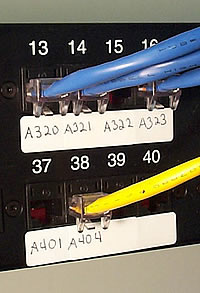
If you really want to be a purist, you can use the official, and rather confusing, labeling methodology; but most real-world networks simply use their own internal codes, as shown in Figure 10-7.
Fig. 10-07. Labeled patch panelPatch panels come in a wide assortment of port types and numbers of ports. You can get UTP, STP, or fiber ports; some manufacturers combine different types on the same patch panel. You can get 8, 12, 24, 48, or more ports on a patch panel.
UTP patch cables also come with CAT ratings, so don’t blow a good CAT5 cable installation by buying a cheap patch panel—get a CAT5 patch panel! Most manufacturers proudly display the CAT level right on the patch panel.
Once you’ve installed the patch panel, you need to connect the ports to the hub through Patch Cables. Patch cables are usually 2- to 5-foot long UTP cables, very similar to horizontal cabling. Unlike horizontal cabling, they use stranded cable to enable them to withstand much more handling.
Even though you can make your own patch cables, most people buy pre-made cables. Making a good CAT5 connection with stranded cable is a little bit harder than with solid core, so buying CAT5 patch cables—yes, patch cables come with CAT ratings too—can make your life easier. Buying patch cables also enables you to use different colored cables to facilitate organization; you might use yellow for accounting, blue for sales, and so on.
An equipment room doesn’t have to be a special room dedicated to computer equipment. You can use specially made cabinets with their own little built-in equipment racks that sit on the floor or attach to a wall. You can use a storage room for this purpose, as long as the equipment can be protected from the other items in the closet. Fortunately, the demand for equipment rooms has been around for so long that most offices have them ready to go.
Well, your basic star is certainly coming along! The EIA/TIA horizontal cabling is installed and the equipment room configured. Now you need to address the last part of the structured cabling system: the work area.
The Work Area
From a cabling standpoint, the work area is nothing more than a wall outlet. The wall outlet serves as the termination point for the network and telephone cables, providing a convenient insertion point for PCs and telephones. The wall outlet consists of nothing more than a female jack that connects to the cable, a mounting plate, and a faceplate.
There are CAT5 rated jacks for wall outlets to go along with the CAT5 cabling in your network. Many network connector manufacturers use the same connectors in the wall jacks that they use on the patch panels. These modular jacks increase the ease of installation significantly.
Most work area outlets have two connectors: one for the network and one for the telephones. Many outlets use RJ-45 for both connections because RJ-11 jacks fit into RJ-45 and many phones use RJ-45 natively. Whatever you do, be sure to label the outlet to show the job of each connector.
Fig. 10-08. Typical phone/data outletA good outlet will also have some form of label that identifies its relative position on the patch panel. It sure saves a lot of work later if you take the time to provide proper documentation!
The last step is connecting the PC to the outlet box. Here again, most folks use a patch cable. Its stranded cabling stands up to the abuses of frequently moved PCs and the occasional kick from the user.
The work area may be the simplest part of the structured cable system, but it’s usually the source of most network failures. When a user can’t see the network and you suspect a broken cable, the first place to look is here!
Earlier I asked why the EIA/TIA 568 specification only allowed UTP cable lengths of 90 meters instead of the 100 meters allowed by most networking technologies that use UTP. Have you figured out why? The answer is the patch cables! They add extra distance between the hub and the PC. That extra distance must be compensated for by reducing the horizontal cabling length.
The New Basic Star
EIA/TIA structured cabling methods transform the basic star into an ordered and robust network, rather than a cabling nightmare like it was at the beginning of this discussion. Sure, you don’t have to do any of this to make a network function; you only have to do it if you want the network to run reliably and to change easily with the demands of your organization.
The extra cost and effort of installing a properly structured cabling system pays huge dividends by preventing nightmares such as trying to locate one bad cable; it also helps protect the network from users.
Chapter 3
Beyond the Basic StarThe basic hub with star is only acceptable in the simplest networks. In the real world, networks tend to have many hubs, and many networks span floors, buildings, states, and even countries. Let’s take the basic star and, using structured cabling where applicable, go beyond it to see some of the equipment and strategies for more advanced, larger, and more efficient networks.
Be aware that I only lightly touch on networking beyond the basic star in this lesson. Network+ wants you to understand the concepts and does not intend for you to be the ultimate expert. Each of these more advanced network topics deserves its own lesson, if not its own book.
Getting a little switchy?
As PCs are added to the basic star running 10BaseT, the network traffic increases. As network traffic increases, users begin to notice a perceptible slowdown in network performance. One of the fastest and cheapest hardware solutions to too much traffic on a 10BaseT network is the addition of a switch.
To switch—sorry, but the pun was just hanging there!—to a switched 10BaseT network, simply remove the hub and replace it with a switch. Nothing need be done to the cards or the cabling. Certainly, switches are expensive compared to a hub, but the ease of installation and the instantaneous positive results make switches very popular today.
Switches, like hubs, come in a dizzying variety of shapes and sizes. From 20 feet away, a hub and a switch look identical. Most manufacturers use the same casing for equivalent hubs and switches. Figure 10-9 shows an Intel small-office hub next to a small-office switch; note that they are virtually identical.
Fig. 10-09. Switches and hubs are similar.The cost of switches motivates a good network technician to use switches as efficiently as possible. There are a number of strategies for implementing switches, each with different benefits. The three most common strategies are to switch all of the systems, switch the servers, or use a switch as a bridge.
Providing every PC a switched port gives the network incredible throughput, but it is expensive and overkill for all but the most heavily overworked networks. To switch just the most accessed systems in any network—that is, the servers—makes more sense for most networks.
Most networks that use switching go for a combined hub/switch with one or two switched ports for the servers and regular ports for the other PCs. Figure 10-10 shows the back of a hub; notice the two switched ports and the regular ports.
Fig. 10-10. Back of hub showing switched and regular portsA third popular strategy is to use the switch as a bridge. This helps compartmentalize a fair-sized network and reduce internetwork traffic.
As an example of when to switch to switches, let’s look at the Bayland Widget Corporation’s three-hub network. Each hub serves a different department: hub1 is for Accounting, hub2 is for Sales, and hub 3 is for Manufacturing. Each department has its own server and only rarely does someone from one department need to access another department’s server. The hubs all cascade from a central, single hub.
Fig. 10-11. Basic cascading hubsAs the network currently stands, every system on the network hears all traffic from all of the other systems. Replacing the central hub with a switch keeps traffic between two systems in one department from spreading into the network in the other departments. Such a setup makes excellent sense for mid-sized to large networks and can reduce the use of network bandwidth significantly.
Multispeed Networks
In Lessons 8 and 9, we touched on the concept of multispeed networks. Making a network faster with higher-speed networking technologies is another great way to combat a slow network.
Simply replacing a basic star’s 10BaseT hub and 10BaseT NICs with 100BaseT, however, has no effect on the basic star. Making every PC in the network faster is usually overkill, the same as making every machine switched. But the more common uses of combining high-speed with low-speed networks most certainly will add new hardware to the basic star.
As I mentioned in Lesson 9, you can purchase a multispeed hub, containing one or two 100BaseT hubs with 10BaseT hubs. You can then give the server a 100BaseT card and plug it into the 100BaseT port to improve performance.
Fig. 10-12. Speeding up the server improves throughput.This is a fine strategy for smaller networks and it doesn’t affect the basic star. Let’s look again at the Bayland Widget Corporation’s three-department network and apply the concept of multi-speed networks. You can use faster networks in conjunction with slower networks to increase throughput. Again, replace the central hub, but this time with a 100BaseT hub. Add the servers to their individual 10/100 hubs or add them together to the 100BaseT hub.
Each scenario provides roughly the same increase in throughput.
Fig. 10-13. Speeding up all the serversThe current hip strategy for improving network speed is to combine both high-speed and switching into a scenario that looks something like the network in Figure 10-14.
Fig. 10-14. Combined switch and 100 MbitIf you look at these advancements to the basic star, you’ll notice that they have one item in common: they all have a special set of cables that are designed to run better than the regular 10BaseT. These cables rarely go to a PC, unless it is a server.
In a way, we’ve got two totally separate types of networks: the individual networks connecting the PCs, and a single, high-speed network that ties together all of the individual networks. This is the backbone.
The backbone is not one cable; rather, it is a group of cables running from a central point—usually a high-speed switch—to all of the other switches or hubs. EIA/TIA doesn’t give a darn about hubs, switches, high-speed or low-speed, but they have a lot to say about backbones—in particular, how those backbones are cabled.
Multiple Floors, Multiple Buildings
Once a network breaks out of a basic star and you begin adding more hubs/switches, certain demands begin to surface. First, the network will need multiple networks with multiple switches/hubs in multiple equipment rooms.
Next, the multiple hubs/switches will need to be tied together with a backbone cable. That backbone will need to be able to support the demands of the combined networks. Finally, mission-critical servers will need to become centralized to simplify administration.
All of these statements can combine into a single statement: “As networks grow, they take up more space!” Adding significantly more PCs to a network usually implies adding work areas: more offices, cubicles, and so on. More work areas means more equipment rooms, possibly on multiple floors. It means new buildings, requiring relatively long distances between any given server and the PC that wants to access it. It usually means more, and more powerful, servers to handle the increased demand.
As more servers come into the network, the administrators of those servers want them placed together in a single room: a computer room. A computer room enables the administrators to handle the mundane chores, such as backups, from one central location. The larger the network, the larger the space needed to support it.
The concept of structured cabling continues beyond the basic star. EIA/TIA provides a number of standards, centralized on EIA/TIA 568 and another important EIA/TIA standard, EIA/TIA 569, that address the issues of multiple equipment rooms, floors, and buildings.
Again, EIA/TIA does not think in terms of networks, and has developed its own terminology for structured cabling beyond the basic star. With a little simplification, EIA/TIA’s view of structured cabling breaks down into six main components: the equipment room, the horizontal cabling, the work areas, the backbone, the building entrance, and the telecommunication closets.
Fig. 10-15. Backbone and building entranceThe first three were discussed above in the basic star and occupy the same roles in a more complex network. Let’s concentrate now on the last three.
Don’t bother memorizing these! Network+ is not going to quiz you on naming each of these parts of structured cabling. Do make a point to understand the equipment involved with each of these parts and how they interrelate. This is real-world stuff that you will need in the marketplace.
Telecommunications closets are really more for telephone systems than for networks, but are included here for completeness. It’s where you connect the individual phone cables running from the work areas to the actual phone lines from the internal telephone system. Before the onset of more advanced telephone systems that handle this electronically, this closet was where you moved lines to change phone numbers in an office.
Have you seen those white little connectors with all the phone lines punched into them? Those are called punch down blocks; according to EIA/TIA, they should be located in a telecommunications closet for telephones.
Fig. 10-16. Punch down blocksTelecommunications closets aren’t supposed to have networking equipment in them, so they are rarely seen for networks. Instead, larger networks will have a number of equipment rooms. From a networking standpoint, telecommunications closets don’t strictly apply—especially for our very short dip into structured cabling.
Most networks have one equipment room per floor. If the room is centrally located in the building, the 90-meter distance will completely cover the floor space in most buildings. The computer room is nothing more than the main equipment room.
EIA/TIA specifies using UTP, STP, or fiber optics for backbones. UTP and fiber optic are very popular for backbones, whereas STP is rarely used. While any cable that meets the criteria for backbone—discussed above and in Lesson 2—is certainly a backbone cable, EIA/TIA thinks more of backbones as cables that vertically connect equipment rooms, often called risers, or that horizontally connect buildings, known as interbuilding.
EIA/TIA gives some guidelines for backbone cable distances, but the ultimate criteria for “How long can this cable be?” depend on the networking technology used.
Fig. 10-17.Fiber optic backbone cables connecting into hubsMost riser backbones use either copper or fiber optic cables. The type of networking technology used determines which cabling type to use for the backbone. Only fiber optic should be used in interbuilding cables due to its imperviousness to electrical problems. Certainly, copper can be used between buildings, but it needs significant grounding to prevent the chance of damage from electricity.
Don’t even think of using copper solutions, namely coax or UTP, for interbuilding links. Differences in the neutral-to-earth voltage—a small voltage that develops at the point where an electrical system is grounded—of two buildings can cause major data corruption problems as well as a potentially dangerous voltage difference between ends of the medium.
The problem in this situation is caused by the ground materials, the water and minerals in the soil between the buildings, which act like the chemicals in a battery. When you string a piece of wire between the two poles of the battery—in this case, the buildings—a current flows between the poles, messing up the data and causing a voltage difference to build up.
The building entrance is where all of the cables from the outside world—telephone lines, cables from other buildings, and so on—come into a building. EIA/TIA specifies exactly how the building entrance should be configured. CompTIA isn’t interested in any aspect of the building entrance other than the type of cable that should be used between buildings: fiber optic.
Network+ does not directly address structured cabling, but understanding structured cabling sure makes a lot of Network+ questions easier. For example, you’re not going to be quizzed on the different types of fiber optic cable, but you should be ready to determine, as the Network+ objectives state, “When they are appropriate.” Don’t get hung up on how UTP horizontal cable is placed over drop ceilings, but do be aware of its susceptibilities to radio frequency and electronic interference.
My goal here has not been to turn you into a cable installer, but to give you a solid understanding of the concept of structured cabling. This is important not only for passing the Network+ exam, but also for your future as a good network support person.
Chapter 4
The Tools of CablingIf you like to play with fun toys—er, I meant tools—then get into the network cabling business! Most network cable installers carry an arsenal of nifty tools to help in the installation and testing of new structured cabling systems.
These tools range from inexpensive crimpers—the tools that put the connectors on the ends of the cables—to multi-thousand-dollar cabling testers that plug into two ends of a cable. The higher end cable testers give acres of detailed information to ensure that the electrical properties of a cable pass a battery of EIA/TIA standards. These tools are indispensable to the folks who install cable, and most of them require significant training to use and to understand.
Fortunately, Network+ does not expect you to know how to use most of these tools, especially the expensive ones. It does expect you to know how to use a few basic cable diagnostic tools so that you can answer the two biggest questions about cabling: “Is this cable good?” and “Is this the right cable?”
You can determine if a cable is good with a cable tester. To locate a particular cable, you use a toner. Let’s look at these two types of network tools.
Cable Testers
As the names implies, cable testers test cables. But before we can talk about cable testers, we have to determine what makes a cable bad. No doubt, if Gidget the hamster chews a piece of UTP in half, that cable should be considered bad. Any time a cable is cut through any or all of the wires, you have a cable break. But other things make a cable bad.
How about if someone crimped one connecter improperly, putting the individual colored wire pairs in an incorrect order? What if a perfectly good cable runs too close to an electric motor and is unable to properly move data? What if the distance between the hub and the PC is too long? These all can make a cable bad.
Cable testers come with a wide variety of functions. Most network administrator types staring at a potentially bad cable want to know a number of things.
How long is the cable? Are any of the wires broken? If there is a break, where is it? Are any of the wires shorted together? Are any of the wires not in proper order, i.e., split or crossed pairs? Is there too much electrical or radio interference?
Cable testers are designed to answer some or all of these questions, depending on the amount of money you are willing to pay. The low end of the cable tester market consists of devices that only test for broken wires. A wire that is not broken can conduct electricity—it has continuity. These cheap testers, usually less than $100, are often called continuity testers. Some cheap testers will also test for split or crossed pairs and shorts.
Fig. 10-18.Simple cable testerThese cheap testers usually require you to insert both ends of the cable into the tester. That can be a little bit tough if the cable is already installed in the wall!
Medium-price testers, around $300, add the ability to determine the length of the cables. They can also tell you where a break is located. These devices, such as the Microscanner shown in Figure 10-19, are generically called Time Domain Reflectometers, or TDRs.
Fig. 10-19. Microscanner TDRThese medium-price testers will have a small loopback device that inserts into the far end of the cable, enabling them to work with installed cables. These are the types of testers you want to have around.
Once you want to start testing the electrical characteristics of a cable, the price shoots up fast, into the $2000 and up range. These professional devices test the critical EIA/TIA electrical characteristics and are used by professional installers to verify installations.
Some have powerful extras, such as the ability to plug into a network and literally draw a schematic of the entire network for you, including neat stuff like the MAC addresses of the systems, IP or IPX address, and so on. These super cable testers, as shown in Figure 10-20, might be better described as Protocol Analyzers. Protocol analyzers are discussed in Lesson 12.
Fig. 10-20. PentaScanner high-end testerThese advanced testers are more than most network techs need. Unless you have some very deep pockets or are finding yourself doing very serious cable testing, stick to the medium-price testers.
When do you need to pull out a cable tester? First of all, a good quality, professionally installed cable rarely goes bad—unless you have a serious hamster problem!
Always assume software problems first. The most important clue that you may have a bad cable is when a user tells you, “I can’t see the network!” They get an error that tells them that no server is found, or they go into Network Neighborhood and can’t see any systems other than their own. Double-check the NIC driver to make sure that it hasn’t magically decided to die, and run the NIC’s internal diagnostic and hardware loopback if possible. If the NIC checks out, it might be a cable problem.
Check the link lights on the NIC and hub first. If they’re not lit, you know the cable isn’t connected somewhere. Try another patch cable to the outlet. Still no good? Then check to see if other people can access the network, making sure other systems can see the shared resource—in this case, the server—that the problem system is trying to access. Use the same logon name and password if possible on other systems to make sure they can access the shared resource. Make a quick visual inspection of the cable from the back of the PC to the outlet. Last, if you can, plug the system into another outlet and see if it works.
If none of these work, you should begin to suspect the structured cable. In most cases, assuming the cable was installed properly and was working previously, a simple continuity test will confirm your suspicion.
Be warned that a bad NIC may generate the same “I can’t see the network” problem. This problem worsens because the problem is usually due to a failure of the port on the NIC, making the NIC’s diagnostics useless. Knowing this, most NIC diagnostics include a test the network diagnostic. This diagnostic makes the NIC send or receive packets. You usually need another identical NIC in another system running the same diagnostic to do this test. On occasion, you can insert a hardware loopback plug into the NIC to perform the test.
Ah, if only broken cables were the worst problem! The rarity of that problem, combined with the relative ease of diagnostics, makes bad cables an uncommon and simple-to-fix issue. But another problem, far more common than broken cables, comes up in every network installation: tracking cable.
Toners
It would be nice to say that all cable installations are perfect—that over the years, they don’t grow into horrific morasses of piled-up, unlabeled cables. But in reality, you will find yourself having to locate—or trace, as most network techs say—specific cables. Even in the best of networks, labels fall off ports and outlets, mystery cables disappear behind walls, and new cable runs are added. Most networks require you to be able to pick out one particular cable or port from a stack.
When the time comes to trace cables, you can turn to a toner for help. Toner is a generic term for two separate devices that are used together: a tone generator and a tone probe. These two devices are often referred to as Fox and Hound, the brand name of a popular toner made by Triplett Corporation.
The tone generator connects to a cable with alligator clips, tiny hooks, or a network jack, and sends an electrical signal on the wire at a certain frequency. A tone probe emits a sound if it comes close to the cable to which the tone generator is connected.
Fig. 10-21. Tone probe at workTo trace a cable, connect the tone generator to one end of the cable, and then move the tone probe next to all of the possible cables on the other end—usually in the equipment room. The tone probe will make a sound when it is place next to the right cable.
More advanced toners will include phone jacks, enabling the person manipulating the tone generator to communicate with the person manipulating the tone probe. “Jim, move the tone generator to the next port!”
Some toners have one probe working with multiple generators. Each generator emits a different frequency and the probe emits a different sound. Good toners are inexpensive, around $75. Cheap toners can cost less than $25, but these usually don’t work very well. If you want to support a network, you’ll own a reliable toner.
Together, a good, medium-priced cable tester and a good toner are the most important tools used by folks who support, but don’t install, networks. Be sure to add a few extra batteries; there’s nothing worse than sitting on the top of a ladder holding a cable tester or toner that has just run out of power!
Chapter 5
ConclusionCable types, connectors, fire ratings, racks and tools: how much of this do you need to know? You’re going to get your Network+ and then work in some network somewhere by just sitting at a keyboard all day, right? Wrong.
CompTIA created the Network+ exam to test for knowledge that anyone working on a network should know. If you work on a network, you will find yourself needing to expand the network and being the first line of defense for problems that come up.
This lesson covers only what you need to know to pass the Network+. It barely touches the vast amount of knowledge and training needed to become a cable installer. Understanding the components of structured cabling, combined with a few basic tools and techniques, won’t make you a professional cable installer, but it most certainly will make you comfortable with the workings of network cabling. Such knowledge enables you to make some basic fixes and to communicate with the pros!
Supplementary Material
The Complete Guide to Structured Cabling
http://www.it-cabling-solutions.co.uk/The aim of this site is to provide a source of information for IT managers and cable installers relating to structured cabling issues.
Switches versus Hubs: Which to Choose?
http://www.3com.com/corpinfo/en_US/technology/tech_paper.jsp?DOC_ID=5326From the 3Com web site comes this white paper on the pros and cons of switches and hubs.
Copyright 2003 by ed2go.com. All rights reserved.
No reproduction or redistribution without written
permission.