
![]()
DATA COMMUNICATIONS
© Copyright Brian Brown, 1995-2000. All rights reserved.
Part 20: WIDE AREA NETWORKING - 2
Analog Modems | Dedicated or Leased Lines | Packet Switching
Integrated Services Digital Network | Frame
Relay
Asynchronous Transfer Mode | Digital Subscriber Line
![]()
![]()
![]() Frame Relay
Frame Relay
Sometimes referred to as Fast packet, it is designed for modern networks which do not need
lots of error recovery (unlike packet switching). Typical Frame relay connections range
from 56Kbps to 2Mbps. Frame relay is similar to packet switching X.25, but is more
streamlined giving higher performance and greater efficiency.
Frame relay, like X.25, implements multiple virtual circuits over a single connection, but does so using statistical multiplexing techniques which yields a much more flexible and efficient use of the available bandwidth. FR includes a cyclic redundancy check (CRC) for detecting corrupted data, but does not include any mechanism for corrected corrupted data.
In addition, because many higher level protocols include their own flow control algorithms, FR implements a simple congestion notification mechanism to notify the user when the network is nearing saturation.
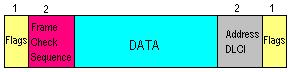
Frame Format
The format of FR frames is shown in the diagram below. Flags define a frames start and
end. The address field is 16 bytes long, 10 of which comprise the actual circuit ID (Data
Link Connection Identifier). The DLCI identifies the logical connection that is
multiplexed into the physical channel. Three bits of the address field are allocated to
congestion control.
FR also supports multi-casting, the ability to send to more than one destination simultaneously. Four reserved DLCI values (1019 to 1022) are designated as multicast groups.
| Advantages | Disadvantages | Common Usage |
| Low incremental cost per connection (PVC) |
Relatively high initial cost |
Interconnecting lots of remote LAN's together |
| Exploits recent advances in network technology |
||
| Supports multicasting |
Additional References
Frame Relay
Resources
Basics of
Frame Relay
![]() Asynchronous Transfer Mode (ATM)
Asynchronous Transfer Mode (ATM)
ATM breaks data into small chunks of fixed size cells (48 bytes of data plus a 5 byte
overhead). ATM is designed for handling large amounts of data across long distances using
a high speed backbone approach. Rather than allocating a dedicated virtual circuit for the
duration of each call, data is assembled into small packets and statistically multiplexed
according to their traffic characteristics.
One problem with other protocols which implement virtual connections is that some time slots are wasted if no data is being transmitted. ATM avoids this by dynamically allocating bandwidth for traffic on demand. This means greater utilization of bandwidth and better capacity to handle heavy load situations.
When an ATM connection is requested, details concerning the connection are specified which allow decisions to be made concerning the route and handling of the data to be made. Typical details are the type of traffic [video requires higher priority], destination, peak and average bandwidth requirements [which the network can use to estimate resources and cost structures], a cost factor [which allows the network to chose a route which fits within the cost structure] and other parameters.
UNDER SONSTRUCTION
155Mbps
622Mbps
Additional References
ATM Frequently
Asked Questions (FAQ)
A Very Cool Java-based ATM
Signalling Simulator (requires Java-capable browser)
IETF IP over ATM Working Group
![]() Digital Subscriber Line (xDSL)
Digital Subscriber Line (xDSL)
xDSL is a high speed solution that allows megabit bandwidth from
tele-communications to customers over existing copper cable, namely, the installed
telephone pair to the customers premises (called the local loop). With the high
penetration and existing infrastructure of copper cable to virtually everyone's home (for
providing a voice telephone connection), xDSL offers significant increases in connection
speed and data transfers for access to information.
In many cases, the cost of relaying fiber optic cable to subscriber premises is prohibitive. As access to the Internet and associated applications like multi-media, tele-conferencing and on demand video become pervasive, the speed of the local loop (from the subscriber to the telephone company) is now a limiting factor. Current technology during the 1980's and most of the 1990's has relied on the use of the analog modem with connection rates up to 56Kbps, which is too slow for most applications except simple email.
xDSL is a number of different technologies that provide megabit speeds over the local loop, without the use of amplifiers or repeaters. This technology works over non-loaded local loops (loaded coils were added by telephone companies on some copper cable pairs to improve voice quality). xDSL coexists with existing voice over the same cable pair, the subscriber is still able to use their telephone, at the same time. This technology is referred to seamless.
To implement xDSL, a terminating device is required at each end of the cable, which accepts the digital data and converts it to analogue signals for transmission over the copper cable. In this respect, it is very similar to modem technology.
xDSL provides for both symmetric and asymmetric configurations.
| Asymmetric | Symmetric |
| Bandwidth is higher in one direction | Bandwidth same in both directions |
| Suitable for Web Browsing | Suitable for video-conferencing |
![]() Variations
of xDSL
Variations
of xDSL
There are currently six variations of xDSL.
| xDSL Technology | Meaning | Rate |
| DSL | Digital Subscriber Line | 2 x 64Kbps circuit switched 1 x 16Kbps packet switched (similar to ISDN-BRI) |
| HDSL | High-bit-rate DSL | 2.048Mbps over two pairs at a distance up to 4.2Km |
| S-HDSL/SDSL | Single-pair or Symmetric High-bit-rate DSL |
768Kbps over a single pair |
| ADSL | Asymmetric DSL | up to 6Mbps in one direction |
| RADSL | Rate Adaptive DSL | An extension of ADSL which supports a variety of data rates depending upon the quality of the local loop |
| VDSL | Very High-bit-rate asymmetric DSL |
Up to 52Mbps in one direction and 2Mbps in the other direction. |
© Copyright Brian Brown, 1995-2000. All rights reserved.
![]()
![]()
