
![]()
DATA
COMMUNICATIONS
© Copyright Brian Brown, 1995-2000. All rights reserved.
Part 8: RS232 Serial Communications
Electrical Interfaces | EIA RS232 | Connectors | Signal Descriptions | Exercise | Transferring Data
Break Out
Box | DTE - DTE | Null Modem | RS232D | Summary | Test 4
![]()
![]()
![]()
Introduction
This section introduces the RS232 Serial standard. This is a
standard that is used to connect serial devices like Modems to a
personal computer. The main features and signals of the standard
will be covered.
Objectives
At the end of this section you should be able to
![]() Electrical Interfaces
Electrical Interfaces
An electrical interface is the connection between two devices.
There are two common data interfaces that specify international
standards for low speed data communication.
![]() THE EIA RS232-C STANDARD
THE EIA RS232-C STANDARD
Specifies a 25 pin connector as the standard interface in data
communication networks, with lettering pin designations for
ground, data, control and timing circuits. The table below shows
the designations for each of the 25 pins of the standard.
| INTERCHANGE | CIRCUIT No. | PIN No. | DESCRIPTION |
| AA | 101 | 1 | Protective Ground |
| BA | 103 | 2 | Transmit Data |
| BB | 104 | 3 | Receive Data |
| CA | 105 | 4 | Request To Send |
| CB | 106 | 5 | Clear To Send |
| CC | 107 | 6 | Data Set Ready |
| AB | 102 | 7 | Signal Ground |
| CF | 109 | 8 | Receive Line Signal Detect/Carrier Detect |
| -- | -- | 9 | Reserved |
| -- | -- | 10 | Reserved |
| -- | -- | 11 | Unassigned |
| SCF | 122 | 12 | Secondary RLSD |
| SCB | 121 | 13 | Secondary CTS |
| SBA | 118 | 14 | Secondary TD |
| DB | 114 | 15 | Transmitter Signal Element Timing |
| SBB | 119 | 16 | Secondary RD |
| DD | 115 | 17 | Receiver Signal Timing Element |
| -- | -- | 18 | Unassigned |
| SCA | 120 | 19 | Secondary RTS |
| CD | 108.2 | 20 | Data Terminal Ready |
| CG | 110 | 21 | Signal Quality Detector |
| CE | 125 | 22 | Ring Indicator |
| CH/CI | 111/112 | 23 | Data Signal Rate Selector |
| DA | 113 | 24 | Transmit Signal Element Timing |
| -- | -- | 25 | Unassigned |
| This diagram shows an RS232 female connector, with the designated signals shown for each pin. |  |
DATA COMMUNICATIONS EQUIPMENT (DCE)
An example of a DCE is a modem. A DCE is
fitted with a 25 pin female connector.
DATA TERMINAL EQUIPMENT (DTE)
An example of a DTE is a computer terminal. A DTE is fitted with
a 25 pin male connector.
There are two main parts, a mechanical and an electrical standard.
For data lines, binary 1 (a high) is represented by -3 volts to -25 volts, whilst binary 0 is +3 volts to +25 volts.
For control lines, OFF is represented by -3 volts to -25 volts, whilst binary 0 is +3 volts to +25 volts.
![]() RS232 Connectors
RS232 Connectors
The following diagram shows the 25-pin connector used for the DTE
interface. It is a MALE connector, which has 25 pins. Beneath it
is the 25 pin FEMALE connector used on the DCE interface. Note
that the connectors have a longer side at the top and a shorter
side at the bottom. This is to prevent the plugs being inserted
into the connectors the wrong way round.
![]() RS-232
Signal Descriptions
RS-232
Signal Descriptions
The interface transfers data between the computer and the modem
via the TD and RD lines. The other signals are essentially used
for FLOW CONTROL, in that they either grant or deny requests for
the transfer of information between a DTE and a DCE. Data cannot
be transferred unless the appropriate flow control line are first
asserted.
The interface can send data either way( DTE to DCE, or, DCE to DTE) independently at the same time. This is called FULL DUPLEX operation. Some systems may utilize software codes so that information may only be transmitted in one direction at a time ( HALF DUPLEX), and requires software codes to switch from one direction to another (i.e., from a transmit to receive state).
The following is a list of common RS232 signals.
A lot of signals work in pairs. Some signals are generated by the DTE, and some signals are generated by the DCE. If you were measuring the signals on a computer which was NOT connected to a modem, you could only expect to see those signals that the DTE can generate.
| The following table lists some of the signal pairs and the device responsible for generating them. |
|
![]()
![]() Something to think about
Something to think about
You have connected an external modem to a computer using an RS232
cable. After loading the application software, it reports
"Modem is not turned on". You check, and find the modem
is turned on. Gaining access to a multi-meter device, which is
used to read the state of pins on the RS232 connection, which pin
do you think you should check to verify that the modem is turned
on?.
![]() How to
exchange information between a DCE and DTE
How to
exchange information between a DCE and DTE
Now, lets look at the sequence that occurs when data is
transferred between a DTE and a DCE. The data can only be
transferred after the correct sequence of signals is followed,
for instance, there is no point sending data if the modem is
turned off. Lets go through each of the steps involved (i.e.,
signal line assertions required) to transmit and receive
characters across the RS232 interface.
TRANSMITTING DATA (DTE to DCE)
Step 1 and 2 are essential to ensure that the modem is on-line and connected to another modem. Waiting for DSR checks that the modem is on-line.
RECEIVING DATA (DCE to DTE)
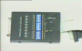
![]() Break-out Boxes
Break-out Boxes
An RS232 breakout box is a device that allows you to monitor the
RS232 connection, and connect various signal lines together. It
is placed between the DTE and the DCE, so you can see the state
of the various signal lines and perform interconnection if
required.
| Using the breakout box is a matter of
determining the signals being asserted and performing
interconnection of signal lines if required. LED's are used to indicate the state of the signal line. RED indicates an active signal (high), and GREEN an inactive signal (low). |
 |
![]() CONNECTING TWO DTE DEVICES TOGETHER
CONNECTING TWO DTE DEVICES TOGETHER
Often, two DTE devices need to be connected together using a
serial link. This is for file transfer or printer access. The
problem is that DTE devices expect to talk directly to DCE
devices, not another device of the same type. DTE's cannot
generate signals like DSR and CTS, so connecting two DTE's
together will result in neither getting permission to send, and
thinking that the modem is off-line (by not receiving DSR).
To allow the interconnection of two DTE devices without using DCE's, a special type of cable must be used. This is called a Null Modem Cable, which fools the DTE into thinking that it is connected to a DCE device. In this case, modems are not used, so the connection looks like.
![]() DESIGNING A NULL-MODEM CABLE
DESIGNING A NULL-MODEM CABLE
In designing a NULL-MODEM cable, the DTE signals from one
computer are swapped over as inputs to supply the DCE expected
signals on the other DTE.
 |
As you can see from the diagram, when two DTE's are connected together, the signal lines from one DTE are transposed to the other DTE, fooling it into thinking that it is communicating with a DCE. |
![]() RS232D (9 pin Connector)
RS232D (9 pin Connector)
The following table illustrates the 9 pin serial connector as
found on most PC's today. This has all but replaced the previous
25 pin connector found on earlier PC's.
| SIGNAL | PIN No. |
| Carrier Detect | 1 |
| Receive Data | 2 |
| Transmit Data | 3 |
| Data Terminal Ready | 4 |
| Signal Ground | 5 |
| Data Set Ready | 6 |
| Request To Send | 7 |
| Clear To Send | 8 |
| Ring Indicator | 9 |
![]() Summary
Summary
The RS232-C interface connects a DTE
(computer) to a DCE (modem). It is a 25 pin interface, where some
signals are generated by the DTE, and some by the DCE. It
supports slow speed data communications. The DTE uses a male
connector and the DCE a female connector.
A breakout box is a device used to monitor or change the state of the interface lines. It is handy in troubleshooting problems. A null modem cable transposes signals so that a DTE can exchange data with another DTE.
![]()
![]() Test 4 [JavaScript]
Test 4 [JavaScript]
Now it is time to review this section and discover how much you
have absorbed. Click on the hyperlink above to begin the test.
© Copyright B Brown. 1995-2000. All rights
reserved.
![]()
![]()
![]()
