|

PLC
Technology
|
 |
The Program Logic Control mainly consists of a CPU, memory
areas, and appropriate circuits to receive input/output data. We can
actually consider the PLC to be a box full of hundreds or thousands of
separate relays, counters, timers and data storage locations. They
don't physically exist but rather they are simulated and can be considered
software counters, timers, etc. |
|
These internal relays are simulated through bit locations
in registers. A PLC works by continually scanning a program. The
scanning cycle consists of 3 important steps. There are typically more
than 3, but I will focus on the important parts.
|
|
Checking Input Status
The PLC takes a look at each input to
determine if it is on or off. Question, is the electrical sensor connected to
the first input on? How about the second input? How about the third? It
records this data into its memory to be used during the next step.
Execute Status
The PLC executes the program one instruction at a time. If the first input was
on then it would turn on the first output. Since it already knows which inputs
are on or off from the previous step, it will
be able to decide
whether the first output should be turned on based on the state of the first
input. It
will store the execution results for use later during the next step.
Update Output Status
The PLC updates the status of the outputs. It updates the outputs based on
which inputs were on during the first step and the results of the scan of the
program during the second step. The PLC would now turn on the first output
because the first input was true (on) and the program was designed to turn on
the first output when this condition is true. After the third step the PLC goes
back to step one and repeats the steps continuously.
|
Program Example
An oil storage tank is filled and then
drained to demonstrate how the PLC controls a process.
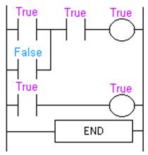
Initially the tank is
empty. Input 0000 is TRUE and Input 0001 is also TRUE.
|
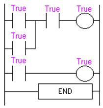
Gradually the tank fills because 500, which is
a pump motor, is on.
After 100 scans the
oil level rises above the low level sensor (Input 0000) and it becomes open
(false).
|
|
Notice that even when the low level sensor (Input 0000) is false there is
still a path of true logic from left to right. This is why we used an
internal relay. Relay 1000 is latching the output (500) on. It will remain
on until no true logic path exists from left to right, which will happen
when the full level sensor (Input 0001) becomes false.
After 1000 scans the
oil level rises above the high level sensor (Input 0001), which becomes open
or false.
|
|
Since there is no more
true logic path, output 500 is no longer energized (true) and therefore the
motor turns off.
After 1050 scans the
oil level falls below the high level sensor (Input 0001) and it will become true
again.
|
|
Notice that even though the
high level sensor (Input 0001)became true there still is NO continuous true
logic path and therefore coil 1000 remains false!
After 2000 scans, the
oil level falls below the low level sensor (Input 0000) and it will again become
true. At this point the logic will appear the same as SCAN 1 above, and the
logic will repeat as illustrated in the simulation below:
|
This is the basis of "how" Program Logic
Control works in modern manufacturing processes.
|