
Note: Apologies to our growing Army of fans about
the delay in updating -
internal politics at the school almost destroyed the whole project.
Following patient negotiations, we are slowly getting back on track.
The visit to Gemini Headquarters was
interesting, and Brian offered
some useful tips on preparing Maximus for his big day.
In the meantime, Cox Plastics (Boldon) had faxed St John's
with details of Lexan Polycarbonate.
We also received details from T A Plastics.
The plan is to use Lexan beneath the flipper, so
that when shields
are raised, the exposed motors will have some protection.
Another sheet would be useful on Max's underside to protect the motors
and electronics from the flame pit and / or other Robots.
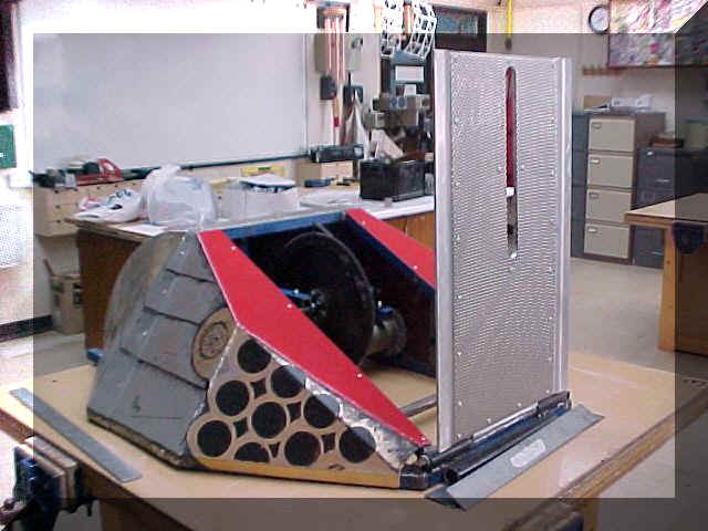
The cylinder can be seen in its final position in the picture
above.
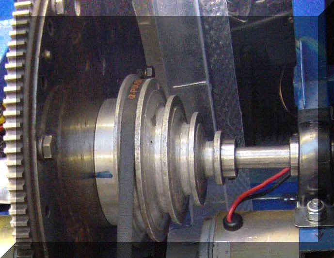
The new mounting for the flywheel motor has been fitted,
as has the first stage of the flipper 'pusher' linkage.
The flywheel will be tested later (in low gear at first), and
its speed measured by strobe.
Then we may try 'second gear' - if we dare!.


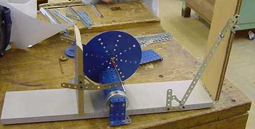
The above set of pictures show the model
used to design the flipper 'pusher' linkage.
Always make a model if you can - it can
save a lot of time and trouble!
Another safety feature we have been meaning to fit, and now
have the time to make, is a 'fire-wall' to protect the batteries and electronics from the
spinning flywheel.
Andrew used sheet aluminium, riveted together, to make a copy of the
makeshift plastic shield (see above) we had used up until now.
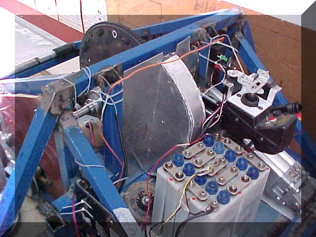
The above pic shows the firewall in place.
Sharp eyed viewers will notice that it is welded together - not riveted as planned.

Thanks go out once again to our friends at Aycliffe
Fabrications for their help.
Thanks John Flanagan and David Spensley!
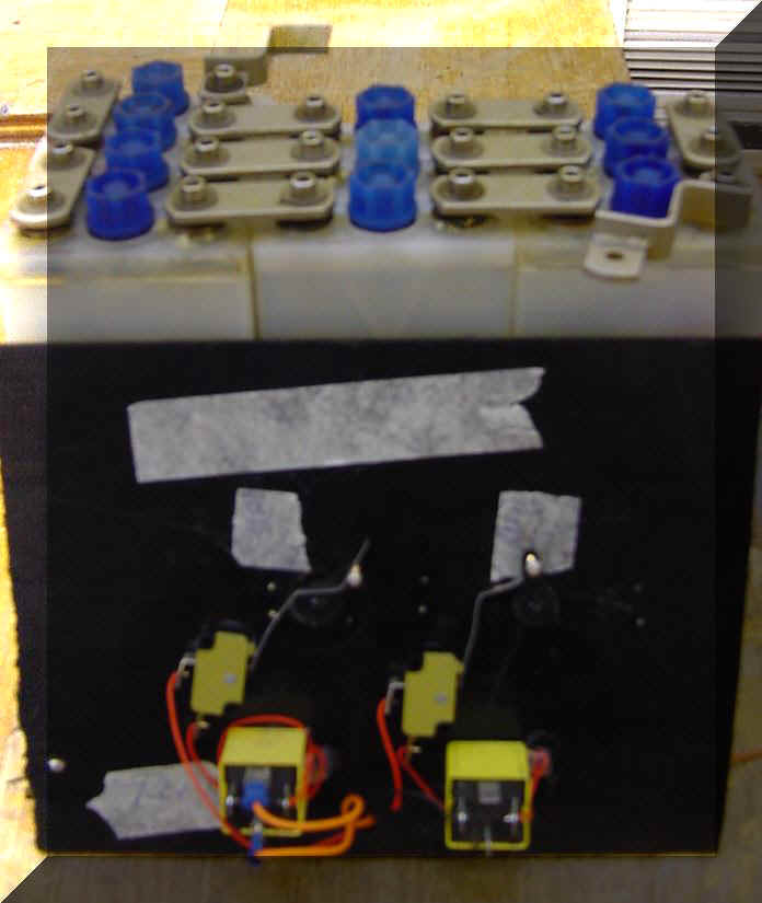
In the meantime, we had put together a
control board to feed power to the solenoid, and ultimately, the flywheel. The
board, along with the SLAB emergency aircraft batteries can be seen above. Remember,
the idea was to trigger the solenoid 'on' with 12 volts, then to 'hold it on' with only
4.8 volts. This split cell arrangement where each cell above produces 1.2 volts
will allow us to do this. The SLABs will also provide loads of power to the flywheel
motor.

The low voltage hold-on idea was tested in
mid-March, and almost worked. We increased the voltage from 4.8 volts to
6.0 volts, and tested successfully! The battery voltage dropped further than
expected when full power was drawn by the starter motor, and caused the original 4.8 volts
to drop below the minimum 4 volts.
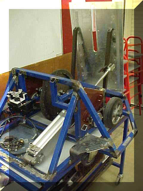
The flipper mounting position is now the next challenge. After much discussion, we have elected to use a simpler and more robust system where the cylinder mounting is fixed directly to the flipper underside. The linkage system worked well enough in theory, but under battle conditions, its possible that it may twist and disable the flipper. It will also save about 0.75 kg.
So we are using the KISS system - Keep It
Simple Stupid!
Here ends this page
