Site hosted by Angelfire.com: Build your free website today!

These pictures are latest progress on top, oldest towards the bottom. I also moved some of the pictures around for better visual flow even though the work wasn't done in this exact order. Captions/descriptions are above the pictures.

  • Click here to watch me almost crash my car at the track. The antifreeze overflow bottle overflowed onto the left rear tire at half track.

  • Click here see then new turbo engine I'm building. So far, this is just checking tolerances. The goal for this engine is 1000hp and pass emissions!

  • Click here see video Putfile link. 23M filesize warning. I have to download the video, once downloaded, close the Putfile page, then click the link again. The video comes right up and plays after that little bit of voodoo for some reason.

  • My half started new webpage at www.turbocarz.com

    Burning tire runs in the family!

  • Have you ever wondered what started this chain of events? I know I fondly look back over the years and a few things come to mind.
  • First of all my parents. I had a great life growing up but things weren't always handed to me. To own a motorcycle for instance meant you had to know how to fix it when it broke down. I remember my early teen years staring at a box of parts my Dad brought home that I paid half for that was supposed to be a motorcycle. If I could build it, I was allowed to have it. Dad made a suggestion to go mow some more lawns to earn enough money to buy a book to learn how to build that pile of parts. I did mow those lawns, buy that book and build that motorcycle, a '73 Husqvarna and it didn't run. I always saw my Dad building things, like EVERYTHING, I knew my Mom was smart being a straight A student and seeing how precise she was with everything, but I never realized how over the top intelligent my Dad was until he helped my troubleshoot that non-running Husky I had just built. Using mostly common sense he talked to me while he isolated the problem to bad magneto electronics. He made finding that problem look so simple. Bigger problem for me, the magneto was encased in plastic of some sort, and not meant to be repaired. I figured that was it for my motorcycle riding any time soon. A new magneto cost more than I paid for 1/2 the bike and it took aver a year to save for that box of parts Dad brought home. Dad broke the plastic away to view the electronic components. He isolated the bad component, replaced it, and epoxied the magneto back together. The motorcycle came to life and breathed fire!!!!! That pretty much got the ball rolling for me.
  • Secondly, look at the picture below. 70 Mach1 with a 351W tuned to perfection by my Uncle Jim, also known as UJ. As you can see, this 351W ran a lot stonger than your typical 351W. Those are no little tires that car is annihilating, those are a pair of like M or N 50's which were quite meaty. The stage was set for me.
  • Finally, my turn. I had to put off my dreams of building a fast car for a while. Getting a degree was more important, so I went straight to college less than a month after high school graduation. No, I didn't like school, I just knew it was something that had to be done and was very important. I wanted to get that part of my life out of my way so I could live MY life. 4 years of college got completed in 3 years going year round. I got a job, paid back all of my loans, then started saving for my dream of build a fast car. Buying a house took my fast car money and I had to start saving money all over again. A house is an investment, a fast car in most cases will not. Fast forward to 24 years later since the dream began... my dream still brews and has a chance to finally come to life. I get a chance to build what has been brewing in my head since my grade school days - that is the time frame I am basing the 24 years from. The combination has changed along the way many times, but what you see starting at the bottom of this page is a good trial version of my dream. That's right this is not the final product, just a test of calculations.

    UJ's 351W powered '70 Mach1 just roasting the hides! What a beautiful sight!!!

    The 351W is out and a very young skinny Mick is standing in place where a 351C would soon go that UJ was building. I wish I had pictures of the 351C UJ built in action. UJ was in his teens when he built that 351C. I could imagine what he would have built with a bigger budget. Best memory in the Mach1: I can remember an open header tire KILLING smoke-fest that started with the Toploader 4 speed in reverse and ended up at the top of third gear with the tires still a blaze, over 7000 rpms and leaving a very impressive autograph on the road that closely resembled UJ's initials which were a pair of really loooooong JJs. Hmmmm, feed that to a young motorhead to be and you'd wait 24 years for your chance to build too.

    Welcome to 24 years later and look who is in my engine compartment! UJ!!! Things just have a way of coming full circle. Many have asked my about this picture since it has been on my turboMustang page while I was building the car. Now you know the story, well some of it anyway. A few perceptive ones have asked why UJ wears his watch so high on his forearm. That is a family speed secret I can not give away... real answer, UJ was in the middle of washing his car when I had him hop in the engine compartment for this picture!

    How's it run? 9.89 @ 136 Update from 9/18-19/05 Ennis Tx, Fun Ford Weekend is below! I'm 1761 in both slips.

    I installed some Christmas presents from my wife. An '04 Mach1 front spoiler was added and some light covers. An '04 Mach1 has a longer nose than a fox body car, so the ends had to be trimmed down to match the wheel well openings.

    Front view. You can see the stylish yard trim two pics up that I was using. LOL!!!.

    Here is the intercooler sprayer in action (below). The picture (above) is the very first run using the CryO2 kit. The CryO2 kit does not add power by itself, but decreases the intake temperature by spraying CO2 directly onto the intercooler. This makes for denser air that will allow more fuel to be burned resulting in more power. A second good effect is I can also run more boost (18psi) and keep the intake temperature at cooler temperatures compared to when I was only running 10 psi of boost. The results speak for themselves.

    As usual, in Mick style, I have to modify everything because I'm like that. The intercooler sprayers normally spray inside of the hoops only. I modified the two hoops I am using to spray both inside and outside of the hoop area. That was a lot of drilling extremely small holes! This modification is to cover more surface area of the intercooler with CO2 while spraying.

    The CryO2 Kit (CO2 intercooler sprayer from Design Engineering Inc.) has arrived. Here is what the kit looks like.

    If you look in the rear view mirrow and see this, it's just me. Honk and give a wave or something. I guess I should level that hood a little too.

    Well. Here's the engine finished except for when a black coupling comes to replace that blue one - just cosmetic. How did the engine cooling work out. So far, very well. I had the car idling in the garage with the hood closed for about 45 mins while tuning and the engine temperature stayed right around the 180 mark the whole time. Ambient temperature in the garage was about mid 90's with sick high humidity.

    Today progress was made to getting the front suspension a little better suited now that all of the weight is in the car. Also made an air dam to help remove heat from the engine compartment and help direct air towards the intercooler, trans cooler and radiator.

    Why can't I just leave things alone? I had to make a turbo support bracket, run a new oil supply line to the turbo and reroute a few other things. Yes. The exhaust is back off of the car. Some changes going on there too, plus I had to test the wastegate.

    The interior is actually in the car and wires are neatly tucked away! I'm going to fall over! I didn't go with the light weight race seats. Maybe I'll install one of them if I need that extra 0.022 of a sec.

    This is why the car still isn't on the road - Wiring up the AEM - and a few other touches to finish up. I thought the picture below of the dashboard was a mess!

    What a mess. Dashboard fun.

    Here the tensioner is installed. (remember this page starts at the bottom and works it's way up. You may have to reload the page to get all the pictures to appear, or right mouse click and "show picture" on the ones that don't appear)

    Get out the sawzall, drill and some sand paper. I made an another alternator tensioner using 1" x 1 1/2" bar stock cut 9 1/2" long. It bolts to the water pump using 3/8" hardware and uses a 3/8" heim joint end to bolt to the alternator. Now I can tighten this baby up good!

    The alternator won't stay tight, so I'm making another tightening bracket. Also had to remove the exhaust for wrapping. You can see the BOV is mounted to some nice 3 1/2" pipe now.

    The rear is back together again. Note - that crush washer was tough on final reassembly!

    Still not right, but getting closer. A good shot of my home made case spreader and ARB air locker.

    Are you tired of seeing this car in pieces yet? I'm am!!!. I'm pulling the 3.73's for some 3.27's.

    Progress was made, but not good enough to start the engine. That blue 90* coupling is temporary until the black one arrives. The reducer where the BOV is mounted has to go as well.

    Here's the crankcase breather and catch can. I had to relocate to the inner fenderwell.

    Q. What is that behind the alternator? A. Knock sensor off of a DSM. That will have to be changed too. The DSM's bore isn't the same as the 302. I'll need something that will give me a filtered input amplitude for the correct frequency using a GM knock sensor off of one of their 4" bore engines.

    Cold side piping laid out.

    One of the last trial fits. Lot of trimming happened behind that bumper.

    The intercooler fins were protected with some cardboard during the many fit tests. The transmission cooler and intercooler brackets are made and installed.

    You know you are having fun when the front of the car is sitting in the living room.

    The intercooler (from Sheren Enterprises LLC) has arrived. 3"in/out. Getting it to fit in the car looks like some good fun.

    Getting the wastegate sorted out.

    Fuel system

    Top end.

    Fuel supply -10 feeding 2 -8's, and -6 return line to the left.

    Another view fighting gravity.

    Not sure if I can run from the tank to the pump against gravity like this.

    Injector testing results!

  • Kalia helped measure the injector flow tonight. We measured weight and mL of volume of each injector. We then calculated both cc/min and lb/hr for sanity. Both came out real close. Here are our injector results:
  • rated 47/flowed 48.6 (test injector)
  • The rest of these are actual flows in lb/hr:
  • 75.7
  • 76.2 high
  • 73.7
  • 71.9
  • 71.9
  • 73.3
  • 71.0 low
  • 72.9
  • The AEM will be used to balance the injectors. Max hp will be equal to the worst flowing injector.
  • Here Kalia models the red topped 47 lb/hr injector vs the blue topped... I guess we'll call it a 71 lb/hr injector.

    My home made injector calibration unit. I hope I don't catch anything on fire or blow up using this. Theory: Wet, drain and pre weight fuel capturing container. Apply 12 volts to pump and get system circulating into a fuel suply. Flick the on switch activiating the injector for a period of 1 minute. Weigh the container with fuel and subtract pre weighed amount. Multiply x60 for lb/hr of fuel. We'll see how well this works later today. I will test a 47 lb/hr injector (shown) and the modified 36 lb/hr injectors.

    Cometic exhaust gaskets have arrived!!!! This company rocks. I went with both types. We'll install the 064AM type first.

    Exhaust port template for custom made Cometic gaskets out of copper and/or 064AM material.

    Flex pipe and center section of the exhaust.

    Downpipe welded and in place.

    Starting to get the exhaust out of the turbo. This was all I could get done after work today before the mosquitos came out and attacked me.

    The remote oil filter set up is completed.

    I added a few special touches.

    This is the remote oil kit.

    Transdapt 1413 this time. This side entry/exit will allow more room for header clearance.

    Partially welded together.

    Mock up fit.

    Turbo has a new home - FINALLY!

    Passenger side exhaust heading to turbo exhaust inlet. It's only tack welded for now, but she's coming together.

    Master Fabricator, Ausimo Glenn holding the passenger side with flex section.

    There, now the whole flex coupling is stainless and I can get back on track.

    This flex coupling From www.roadraceengineering.com is stainless except the ends. I have everything stainless, so I cut the ends off.

    Welding and grinding the new flange shape to match the AFR heads. The port on the left has initial fill welding and rough cut. You can see the port on the left starting to take shape. The port on the right has just one pass of fill weld, no rough cutting. We're seeing at least one more welding and grinding pass to match things up correctly.

    FMS M-9430-P50 stainless steel shorty header. That poor flange got mis-shaped from the welding. The welds are strong, but the shape is nothing close to what the AFR heads really are, or even what a Ford head shape is. How did anyone let that out of the shop and make it to a customer's hands???! The headers flange varies from 0.96" - 1.05" wide and from 1.30" - 1.43" tall. For a comparison, the AFR head exhaust ports measure 1.33" wide and 1.38" tall.

    The reducer and exhaust clamp are made. The clamp is made from the band that was cut from the reducer after it had been resized. I'm not one to waste materials. This is 304 schedule 10 weld "L's". I'm not a welder, nor have had any formal training, but I think these pieces will hold.

    Cutting the reducer to header flange size.

    Reducer is tack welded, ready for cutting.

    There is now a small amount of clearance between the alternator and the header flange. Suprise! I decided to use the alternator bracket I modified instead of the lame looking bolt even though it took a bit of cutting and welding on the header to make it all fit.

    Header flange is removed so it can be rotated 90 degrees and the header outlet angled more downward.

    I'm thinking of putting the turbo here

    Turbo and friends have arrived! The turbo ended up being a GT4067HPS

    The alternator hit the headers, so I had to ditch the bracket all together and use this really lame looking bolt

    I didn't like how the alternator bracket looked 2 pics down, so I cut a little more off of it

    The alternator now goes where the air pump is supposed to go

    I had to modify the stock alternator bracket so the belt wouldn't hit the water pump

    Starting to look like an engine bay again. Still tons left to do

    The front wheel now sits 1" forward with the QA1 K member.

    The bumpsteer kit straightened out the steering goemetry and the wheels no longer sit toed in. I ordered the M-3130 Ford Racing Bumpsteer Kit. The stupid thing has Made in China stamped on it! I think the world is going to end soon.

    The alignment begins. Thanks to crew chief Glenn Breem for this great technique and hours of labor

    The coil overs are installed and rough alignment completed

    Flaming River Rack fits. Now I can get back on track

    Too bad the motor mount hits the steering

    Not pulled too tight anymore

    The steering shaft had to be modified

    Dave looking for room to pull the steering foreward

    The flexible doughnut is not happy

    Driver side notch for K member

    Transmission cooling lines are run

    The engine and transmission are in

    The engine I built is patiently waiting

  • Cometic three layer stainless steel 0.043" viton coated head gaskets
  • Schubeck hydraulic lifters. 0.015" movement for high rpms @ 0.001" backlash
  • studded top and bottom
  • girdled/windage tray
  • -13cc forged lightweight pistons
  • rotating assy balanced within 1 gram
  • lightly modded/ported AFR 165 58cc heads with +0.100 Chevy valves & 1.94" intake
  • pte67hgtq turbocharger on the way!

    C4 ready to go with my home made lines

    Sumped tank coated with rubberized sealant

    What started this whole thing? The two cracks in cylinders 2 and 3 were causing many blown passenger side head gaskets. 8, 10 secons runs was a typical number between head gasket changes. That got old in a hurry!

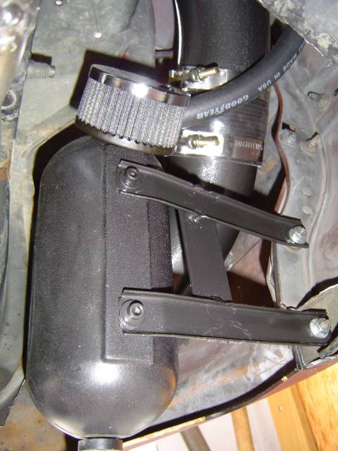
    QA1 front suspension install

    • Ouch!
    • Cut!
    • cut again!

    More Web Sites

    Parts for Sale
    Mick's Home Page
    Mick's Mustang main page - needs updated
    Muscle Mustangs of Brevard County - Mustang Club
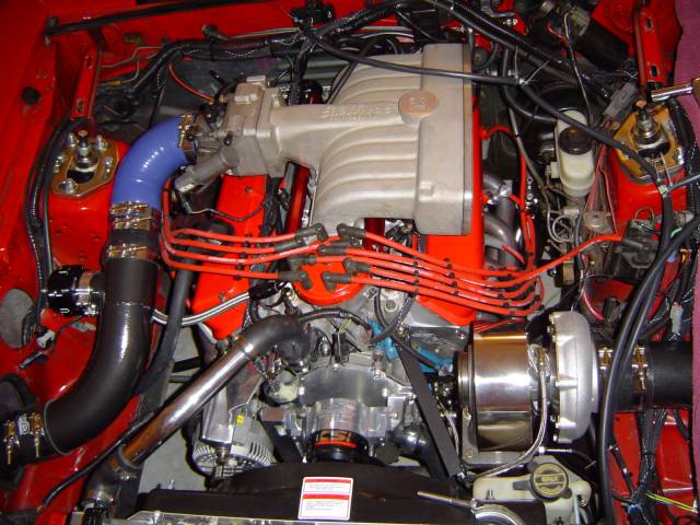
    DSMotorsport - where I bought my turbo

    Updates to follow! Thanks to all of my friends that helped, continue to help and for the moral support from everyone so far.

    Email: Mick