
This page is intended to offer some tips on soldering, some basic math for calculating resistor values and some basic linesar circuits. Remember, I am not exactly an expert but Ive been doing this a while and I work as an electronics technician in Florida. I took some basic electronics classes in high school and college.
First of all if you dont have any experience soldering just practice on some wire.
I reccomend you coat all surfaces to be soldered with a small amount of solder before completing the connection.
This is refered to as "tinning" . The purpose of this is to make the
final connection cleaner and to ensure the solder has bonded with the metal. My basic philosophy with soldering is " if it looks
bad it probably is bad.
Most solder has what is called a flux core this is a liquid material that helps to prevent the connection from being contaminated by oxidation. You will quickly notice that if the flux has burned off it will be very difficult to get the solder to bond with the material. always be sure to use enough to ensure a quality solder joint. You can buy liqid flux as well and sometimes this is useful for soldering larger wire or PC board mounted components, as the flux core is not enough.
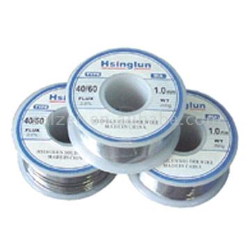 Example of some solder
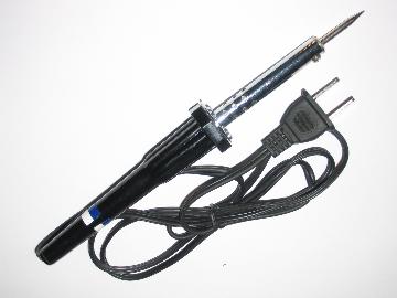 Example of a soldering iron
LED's
Light Emitting Diodes can come in many different varieties. The ones I used are rated at 3.6 volts of drop and they consume .025 amp. They are very reliable and and virtually indestructable. I have heard of them running for 10.000+ hours. I used a multi-meter to test the LED's it has a convenient LED test point where you simply insert it into the openings and it lights and rates the diode. It also tests transistors the meter was the best $20 I ever spent.
For all these calculations I use the values of the LED's I bought yours however
may be different. Specifications for LED's can vary greatly, consult the
manufacturer or packaging for more information on your components.
Ohm's Law
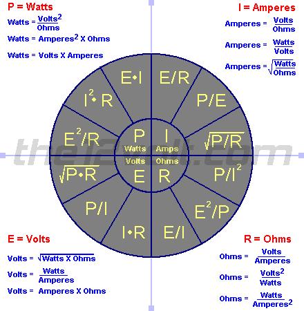
To calculate resistor values you use Ohm's law which is R=V/I where R stands for resistance, V stands for voltage and I represents amperes/amps.
You can also refer to this chart for any conversion you want. I got this at the12volt.com another great resource.
For example for a single LED you have 3.6 volts and .025 amps.
Take this and subtract it from your 12 volt source (the battery) giving you 8.4 volts you need to drop so 8.4/.025 = 336 so I used the closest value to that available which was 330 ohm's.
If you are using LED's as lighting somewhere else Remember that the resistor is going to regulate the voltage differently depending on what kind of load is being drawn. As you may know the vehicle is not always putting out exactly 12 volts, because of the alternator. I suggest using a 12v regulator as these are fairly cheap and provide your circuit with some protection. I got mine at radioshack for $5.00 (USD). This will keep your LED's at a constant current leading to longer life and more consistent light.
For Example at 12v the 330 ohm resistor will drop around 8 volts depending on the tolerance. at 15v you would need a 600 ohm resistor to get the same voltage drop.
For a chart of resistor color codes check out this page
The regulators are pretty much all the same. Basically, they all have three pins one for the incoming voltage, one for the output voltage and one for earth ground, there should be a pin diagram on the back of the package with all the other specs. They have a minimum input necessary for them to operate usually just above 12v. I buy the ones with an internal fuse so it will blow and protect anything down line. Usually they can accept up to 30+ volts coming in so you should'nt ever have to worry about that as the alternator tops out about 15v-18v. They are usually only rated for an amp or so but again LED's draw very little current.
