Site hosted by Angelfire.com: Build your free website today!

Quad Throttle Body Inlet Manifold

This section is dedicated to providing further details on the quad throttle body inlet manifold we made. A number of people have inquired about it, hence I have centralised the information. :)

For more detailed information on how we went about fabricating the manifold, see the Technical Details page.


Front face of the Manifold

Here is the front face of the throttle body manifold, where the carbies bolt on.

The manifold started life as 2 x 20mm thick plates alloy plates. Over a month or so they were:

  • bolted together with three counter sunk cap screws (alan key bolts);
  • marked to indicate where the inlet ports of the head would meet the bottom plate and subsequently where the carbies needed to be mounted to line up as closely as possible with the ports;
  • marked with all the necessary mounting holes (for the manifold to bolt to the head and for the bolts to mount the carbies to the manifold);
  • the top plate (which mates with the carbies) was shaped appropriately;
  • all the mounting holes were drilled;
  • a hole saw was used to cut through both plates to form the the initial ports in the manifold;
  • the manifold ports were die ground to shape;
  • the bottom plate was milled (see the Bottom View section below);
  • the mounting bolts for the carbies were installed;
  • the throttle position sensor (TPS) brackets were made and welded on;
  • finally, the plates were permanently bolted together after the gap between the plates was sealed with Permatex Ultra Grey.

    The process was obviously more complicated than it would first appear, but it's definately not rocket science. Patience was the key.

    One of the important things to note in this view is the carbie mounting bolts. The carbies were initially mounted using studs which were tapped into the bottom plate. Problems arose with this arrangement as the thread in the bottom plate stripped with surprising ease. A great deal of care was taken in the inital cutting of these threads, but none the less, the resulting thread was very weak, possibly indicating poor quality alloy plate.
    Subsequently the manifold needed milling and this cause all sorts of problems with the studs, which sat perpendicular to the bottom plate. It was decided to replace the studs with bolts. This involved re-drilling the holes in the top plate, cutting recesses in the top plate for locking nuts to go on the new bolts and cutting recesses in the bottom plate for the head of the bolts. The bolt heads were ground into an almost rectangular shape, with matching recesses, so as to ensure that they didn't turn when the carbies were being mounted. A view of this is at the bottom of the Quad Throttle Bodies Page.


  • Bottom View

    This view makes it clearer how the bottom plate was milled.

    Initially, both plates were of the same thickness and were bolted parallel to each other. As the manifold progressed it became obvious that the there wasn't enough clearance under the bonnet for the airbox - that it was going to hit the bonnet when the engine rocked. This was somewhat surprising at first, as the carbies had been dummied up with wood to check this.......although this had obviously been done inaccurately.
    At this point, the top plate had been cut out, drilled and ported - hence making another plate wasn't an option. Instead, whole setup was taken out to Brian at Neal Bates Automotive, where we mulled over it. Brian eventually recommended that the bottom plate be milled at an angle. This was going to cause some minor headaches with some of the holes subsequently being offline, but it was a small price to pay in comparison to making a new top plate. The manifold was left with Brian and you can see the result. Perfect, in my humble opinion. :) I was initially concerned that the milling of the plate would cause problems with flow delaminating from the walls of the manifold (due to there being a steep wall angle in the transition from round to oval ports), but this proved unfounded. The ports did need some very minor reshaping, but it was all of 2 hours work.

    The whole arrangement now fits very nicely under the bonnet and you can look from the trumpet and clearly see the back of the valve, with the butterfly's open.
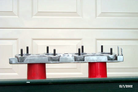

    Side View

    This side view gives a good indication of the change in angle the milling of the bottom plate gave. The bottom plate was milled so that the upper edge was left at the original 20mm thickness, while the bottom edge was reduced to around 5mm thick.


    Back to Car Details :: Exterior :: Interior :: Interior 2 :: Front Brakes :: Front Brakes 2

    Front Suspension :: Rear Suspension & Brakes :: Head :: Induction :: Quad TB Manifold