
 To
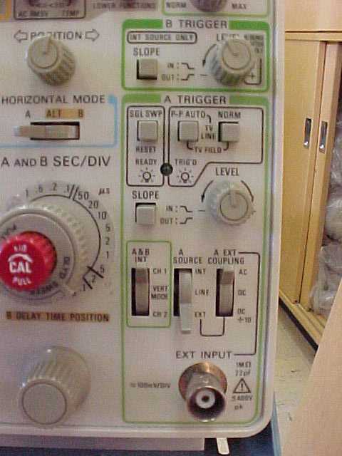
learn basic triggering of the Tektronix 2236 oscilloscope, there are three
switches that you need to know about. These switches are located close to
the bottom of the triggering section of the scope, they are labeled A & B
INT, A SOURCE, and A EXT COUPLING. The A SOURCE switch is used to control where
you trigger the scope from INT, LINE, or EXT. The A EXT COUPLING switch is
used to control the external trigger.
To
learn basic triggering of the Tektronix 2236 oscilloscope, there are three
switches that you need to know about. These switches are located close to
the bottom of the triggering section of the scope, they are labeled A & B
INT, A SOURCE, and A EXT COUPLING. The A SOURCE switch is used to control where
you trigger the scope from INT, LINE, or EXT. The A EXT COUPLING switch is
used to control the external trigger.
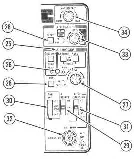 |
25. A Trigger Mode Switches
|
