The Teddybear Cottage.
The Teddybear Cottage started out to be my woodshop. When it proved to be too small for that purpose Sue agreed to buy it from me and I bought a larger building to be used for my shop.
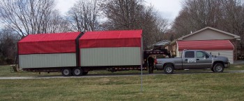
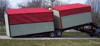
The building was delivered on January 30, 2007 when the temperature was about 20 degrees with a wind chill of zero. There were two identical buildings on the trailer, one for me and by a sheer coincidence, the other was for someone a short distance up the road from us. We can see it as we drive by.
|
|
|
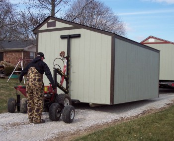
The trailer was parked in the driveway belonging to a neighboring farmer. The trailer was tilted until its tail was dragging on the ground. It was pulled forward leaving the building sitting on the gravel surface.
|
A machine that is basically a two wheeled fork lift, which had been stored inside the building, was moved around to one end of the building. The "T" shaped stop presses against the wall of the building and makes it possible to lift the building. The "T" stop is heavily padded. The end of the building was lifted and an axel inserted underneath. The extra set of tires in the picture belong to the axel.
|
|
|
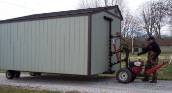
The machine was then moved to the other end and that end lifted. Now the building was on 4 wheels powered by the engine on the machine and can be moved by one man. In fact the whole operation was accomplished by a lone man.
|
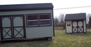
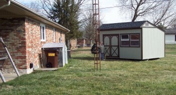
Here the building is seen passing the lawnmower house. Note the similarity in appearance.
|
|
|
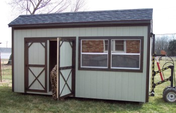
We had this building set on concrete blocks. The delivery man placed a level inside the building and inserted shims between the blocks and building frame to level it.
|
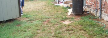
The building was placed at an angle to avoid covering the underground electric service line which runs in front of the building. It comes to the main house just beyond the airconditioner unit.
|
|
|
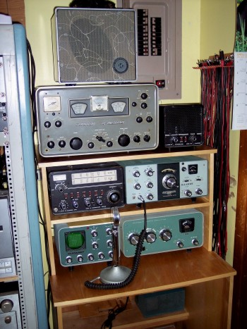
At this point there was no electric wiring to or in the building. It was also still my workshop. An extension cord stretched from an outdoor outlet on the carport provided energy for power tools and lights. I completed this radio desk in the shop. The desk is made of Burch plywood and finished with clear polyurethane.
|
While working on the radio desk it became apparent that this building was too small for a decent woodworking shop. As I worked on the desk I took up most of the floor space. There wouldn't be enough room for a workbench, table saw, drill press, and other equipment I would need. I was beginning to eye the Shop Smith, but even that would not leave any room for a workbench and tool storage space.
It occurred to Sue and me at almost the same moment. Why not sell her this building and get the biggest one the Mennonites make, a 12 by 30 foot one that looks like a garage. The transactions were duly made and the Shop Smith ordered. She agreed to work with me on wiring and finishing my shop after we did the same to her building, hereafter called the teddybear cottage.
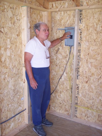
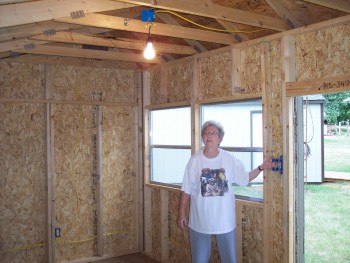
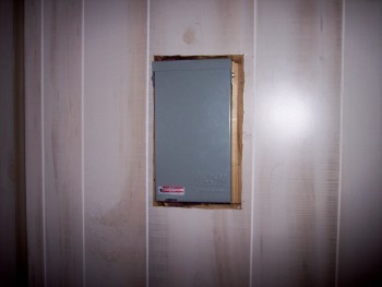
Getting electricity required adding two 240 V branch circuits to the breaker box in the house. The box is located on the other side of the wall where the airconditioner unit is located. I did the wiring for both at the same time although only the teddybear cottage will be shown on this page. The wire comes down from the box into the crawl space and finds its way out through a hole that some now unknown HVAC installer had knocked through the bricks many years before we owned this house. See where the black refrigerant pipes go from the unit to the hole in the wall. The gray plastic LB makes the turn and the conduit goes down into the ground. It runs underground and emerges under the teddybear cottage on the left about half way between the front and the 2 by 4 end which can be clearly seen. This particular picture was taken well after the fact of the installation. In the pictures below that one, that's me with my hand on the breaker. The box provides two 120 V 15 A circuits. The next one is of Sue basking in the warmth from a 200 watt light in a temporary socket. This also shows how unfinished the cottage is on the inside.
|
|
|
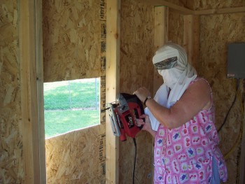
We began finishing work on July 5, 2007. The first step was to install an airconditioner.
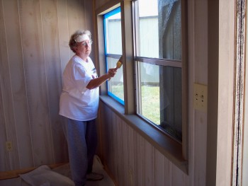
I don't like the idea of installing airconditioners in windows. Windows were meant to look through and an airconditioner can work just as well if installed in a hole in the wall. Of course, this is best done before the installation of insulation and paneling.
In the upper picture you see Sue still holding the saber saw just after finishing the cutout in the siding. Her somewhat unusual headdress is the result of an accident two days earlier in which she got a grain of sawdust in her eye and it became so embedded that she had to go to the doctor to have it removed. She vowed that it would never happen again.
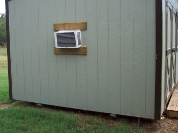
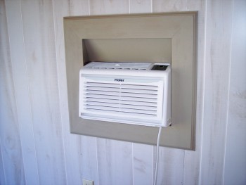
The AC is primarily supported by two pieces of lumber which are fastened to the studs by woodscrews. Two more on the inside will prevent its removal via the midnight requisition.
|
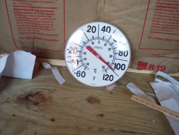
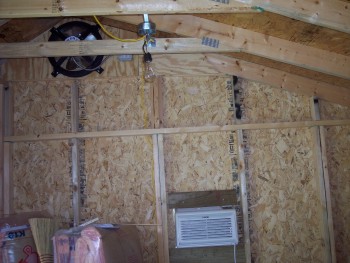
We now had electricity in the cottage and an airconditioner but we couldn't run it. The reason was there was no insulation. Closed up it was like an attic. The AC couldn't even make a dent in the heat. Add to that, we were in the middle of the worst heat wave in this part of the country since the 1940s. The doors and windows were open and an industrial strength fan blowing when the picture of the thermometer was taken.
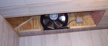
The cottage came with gable vents so we installed a fan in one of them to keep the attic from getting up to 130 degrees on days like this.
You will also notice that the blue plastic electrical box has been replaced by a metal one that is rated to hold up a 125 pound ceiling fan. A fan, not that heavy, does eventually get mounted on this box.
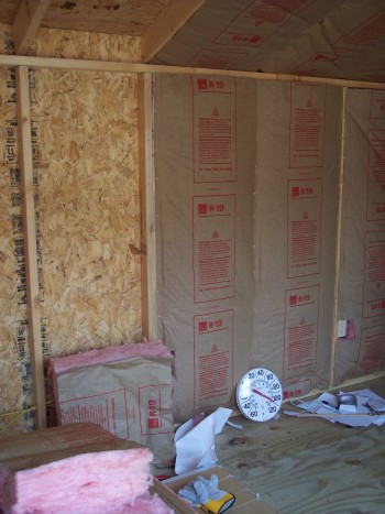
Next it was time for the insulation. We bought a cheep electric staple gun for the task. It also shoots brads and we used it for the paneling too.
|
|
|
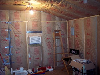
Completing the installation of the insulation gave two benefits. We could close the doors and run the airconditioner, and we could start on the paneling which meant we were on the home stretch.
You've heard it said "measure twice and cut once". No matter how many times we measured, the paneling refused to come out right. I am told this is the reason molding was invented. You can hide a multitude of sins with those little strips of wood.
The bottom picture of the circuit breaker box shows what a disaster our first cutout turned out to be.
|
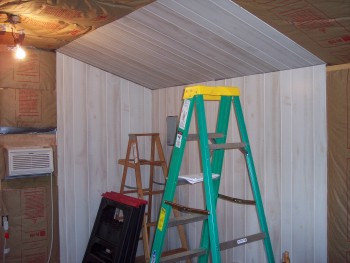
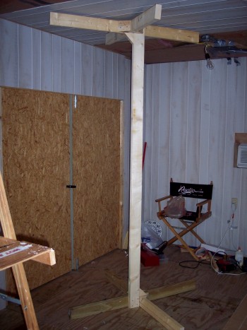
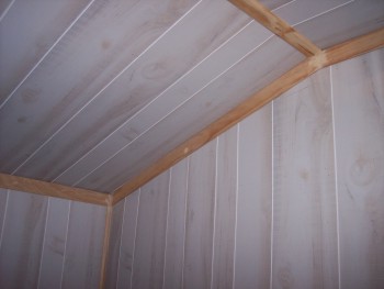
The wall paneling wasn't too bad, neither was that sloping ceiling. The edge of the panel could be rested on the top plate of the rear wall and nailed in place with the electric brad gun. However, when it came to the horizontal part of the ceiling, it was a different story. Sue and I were up, each on our own stepladder, and trying to hold the 4 by 6 foot piece of paneling in place, getting it lined up, and driving a couple of nails to hold it in place. NO WAY!
So, we invented Woody. It took us a couple of hours to cut the pieces and figure out how to put them together. Then we took the pieces into the cottage and assembled it inside. We had to disassemble it to get it out when we were finished. Woody helped us by holding up the panel about 2 inches below the ceiling joists. Then we could shoot brads to hold it in place. Woody will be reassembled and used again for the ceiling of my shop.
|
|
|
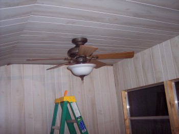
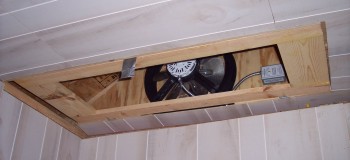
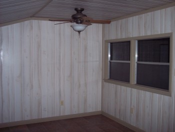
One of the fans was mounted and that meant we no longer needed the industrial strength fan mentioned earlier. The other one had to wait for the access hatch for the attic fan to be completed.
|
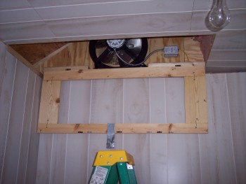
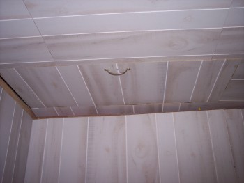
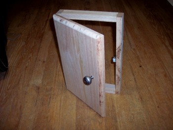
I felt it was unwise to just nail up the ceiling panels and close up the attic fan with no access. An opening was left in the ceiling paneling and a frame built. This frame was hinged to two pieces of 2 by 4 that were mounted below the fan and on a level with the ceiling joists. A piece of duck tape insured that the door could be opened after the paneling was nailed in place. Magnetic door latches of the type used in cabinets were used to hold the door closed. The addition of a handle and insulation on the top side made it complete. The other ceiling fan could be installed and due to our marvelous planning, the door did not hit the fan blades when pulled down.
|
|
|
Next, the floor. The floor provided by the builders was most unsatisfactory. First of all, some of the pieces of plywood were thicker than others. There were large headed nails driven in at an angle. The ones that were straight kept popping up. No matter how many times we pounded them down they kept rearing their ugly heads again.
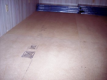
We put sheets of 3/4 inch MDF over the old flooring making sure not to use the same layout so seems would not coincide. It was fastened down with liquid nails and woodscrews in the corners. It came out nice and flat.
|
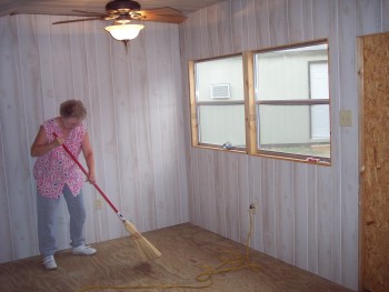
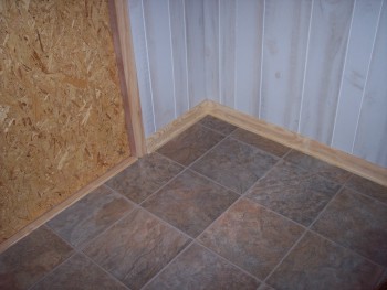
Here, Sue sweeps the MDF sub-floor before the lock-together tiles go down.
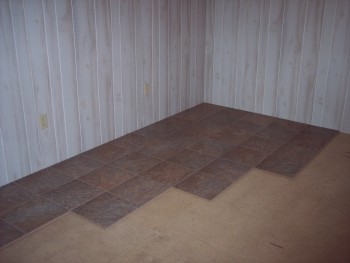
The tiles are approximately 4 feet by 1 foot and have edges something like a tung and groove with a catch on the tung that catches in the groove and holds them together once locked in place. The instructions say to alternate the short seams which gives a stair-step appearance.
The first row was just laid down and locked together working right to left. To start the second row the first tile had to be cut in half. These went down and the third row started with another whole tile.
It wasn't quite as easy as the salesman said it would be. The long edges were fairly easy, just lift up the edge of the tile, lock it to the previously laid one and lay it down. It would lock in place. That was OK for the long edge but the second in a row, and all subsequent ones to the left, required that the newly added tile had to be slid to the right without being lifted up to engage the short seam. One of the half pieces was pressed into service for this. It was placed against the short seam which matched so considerable force could be put on it without damaging the wanted tile. The cut end could be pounded on with a hammer to force the good tile to move and engage the next one down. Then the "tool" could be removed leaving an undamaged edge for the next one in line.
When the wall on the left was reached a tile had to be cut to fill the remaining space. The "tool" could not be used here because all the space had been filled. The tiles had to be cut short enough to allow something to be wedged in between the end of the tile and the wall to force it to the right. We started by prying with a large file but that wouldn't go far enough. Next we inserted the claws of a claw-hammer into the crack and pried against the wall. This resulted in some damaged paneling and also broken edges of the tiles. Most of the damage was covered by the base board and quarter round but there are still a couple of broken places showing both in the paneling and the floor tiles. Some well placed furniture will cover these mistakes.
It seems impossible to make the last one in line lock in place without doing some damage to the wall and tiles. I wonder how the hell the pros do it.
|
|
|
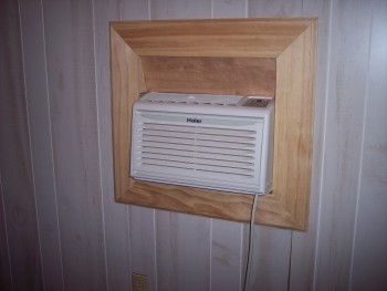
The airconditioner presented a special problem. Manufacturer's instructions called for a 5 degree tilt outward to allow condensed water to properly flow to cool the condenser coil. This placed the vent partly inside the wall. Part of the solution can be seen in the edge of the picture of Woody, and in earlier pictures above. A piece of plywood mounted at an angle deflects the air out into the room.
The molding covers the insulation and imperfections in cutting out the opening in the paneling. Two triangular pieces of wood complete the air escape path and hide what should remain hidden.
|
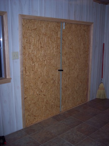
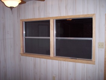
Standard door and window molding and a window sill made of 3/4 inch board, not plywood, and a piece of 3/4 inch symmetrical molding give both a finished look. Compare this with earlier photos in which the door and window show in the background.
|
|
|
When I was very young I remember my mother and father calling this mop board. For many years I have called it base board and quarter round. Sue informs me that today it is called the base and the quarter round is called the shoe. What ever you call it, it hides many mistakes and just plain screw ups as noted earlier.
|
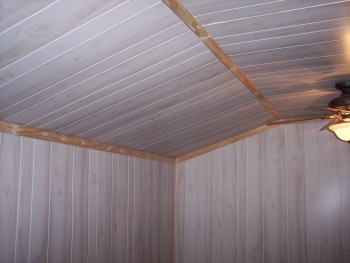
Molding around the ceiling, along the transition from sloping to horizontal, and in the corners brings the project close to completion. Sue has filled the nail holes and cracks where two pieces of wood join with wood filler and sanded prior to painting.
|
|
|
Now we come to painting the wood molding. That's left up to Sue because of her superior vision. In case the color doesn't quite come out on your screen, it is a gray with a slight brownish tint.
|
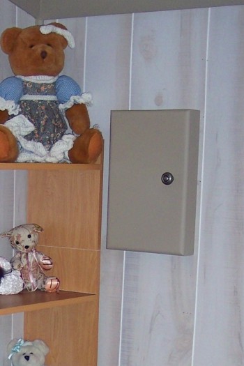
Now back to that pesky circuit breaker panel cutout. We decided to hide it with something like a wall mounted medicine cabinet except that, this one has no back, shown at top right. Once painted and mounted on the wall it covers the electrical box and the cutting mistakes.
This close-up also shows the construction of the display shelves and desk top that are built at one end of the cottage. It is made of finished shelves from one of the local DIY home centers. They are low density fiber board with some kind of plastic covering. We could only get them in 4 foot length and we wanted the sides to be taller than that. The joinery is a biscuit joint. It didn't come out as good as I had hoped. The shelves are fitted into dados and held in place by screws from the outside, which cannot be seen.
The three teddybears are, from top to bottom, Dolly, Tapestry, and Gwaine.
|
|
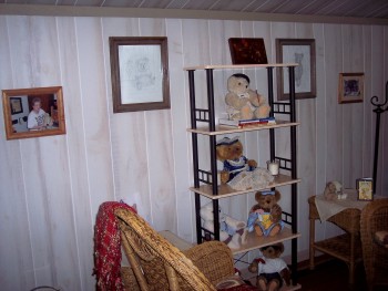
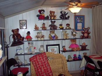
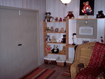
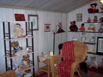
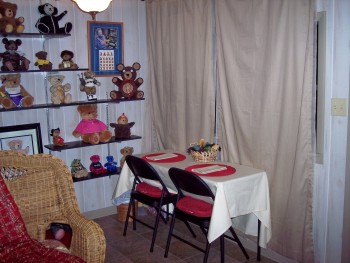
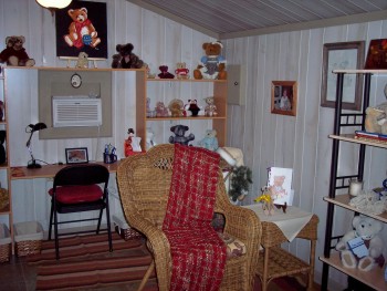
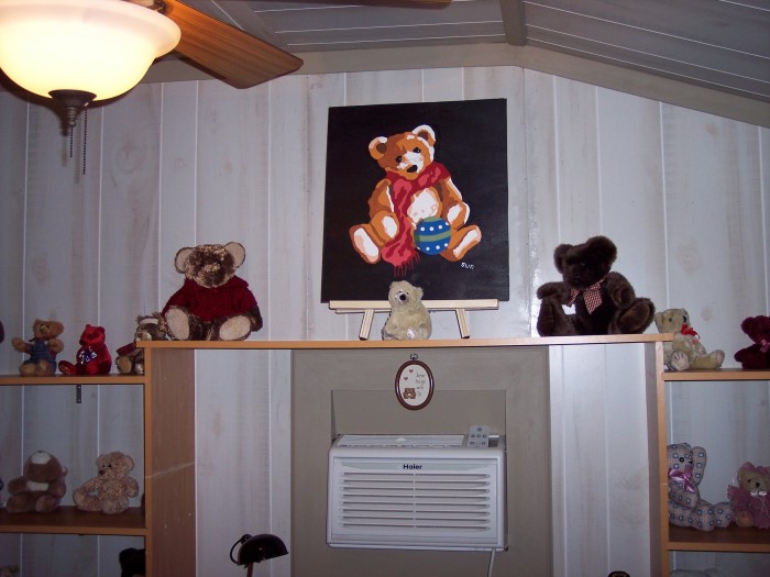
Here is the finished product. This is a full 360 degree panorama moving to the right around the cottage. It was pronounced finished on November 5, 2007. I am typing this on the eve of Thanksgiving 2007. We are both thankful that the job is done.
Sue painted this picture on a piece of quarter inch plywood. My next project is to make a frame for it.
THE END.