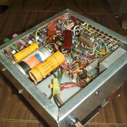
As you can see from the photo it's really crammed and when (not if) I have to repair it some day I will curse myself. I don't know if you can tell from the picture but I left some of the larger capacitors on long leads so I can pull them out to gain access to what's underneath.
All rectifiers are solid state bridges. I didn't want to expend the extra space and waste the power associated with vacuum tube rectifiers.
This power supply was designed with solid state rectifiers so there is no problem. If you were to decide to use vacuum rectifiers you would have to get a power transformer with a higher voltage to equal the performance of this unit. As always I used what I had on hand.Aside.
Back in the late sixties and early seventies it was fashionable to replace tube rectifiers with plug-in solid state replacements. The ads for these plug-ins went something like this. "Get higher efficiency, less heating of the power transformer and better performance". What you got with these replacements was anywhere from 50 to 150 additional volts of B+. This caused all the other tubes to draw more current thus placing a greater load on the power transformer and causing everything to run hotter. In the case of audio power amplifiers they would deliver quite a bit more power for as long as they continued to work. Even high end test equipment, such as Hewlett Packard and General Radio, had problems. This high class gear used electronic voltage regulators not unlike the one found in this power supply. While the voltage applied to the working tubes remained constant the voltage drop across the pass tubes could be as much as doubled. Doubling the power dissipated by the tube would often exceed its maximum rating and it was not uncommon to look into a Hewlett Packard signal generator and see the plate of the pass tube glowing red.If you have some antique electronics equipment DO NOT replace the vacuum rectifiers with solid state. If the replacement has already been done get on the web, buy the original rectifier tubes and put them back in!
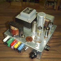
The main positive power supply delivers approximately 400 volts DC @ 110 mA. Because the 5 V 2 A rectifier filament winding is not being used you might think that more current could be drawn from the other windings. Well, that's only 10 watts and you likely could get a little more current out of each winding but don't try to get the whole ten watts out of one winding. In my opinion considering the fact that no new transformers of this type are being manufactured today it's best not to push your luck. Stick with the original ratings.
The floating power supply which provides voltage to the screen grids of the 6AQ5 pass tubes uses a 120 volt transformer. Chances are the one you have or can find will have a 6.3 volt heater winding instead of the 12.6 volt one on mine. Don't forget to wire the heaters of the 6AQ5s in parallel instead of series.
All of the filter capacitors are oversized. The result of this is that the ripple in the regulated output is too small to measure. You could probably go down to a half or even a quarter of what I used and still get satisfactory performance. On the other hand if you're the kind of person who likes to have ripple so small you can't measure it then stick with my values. You definitely don't need to go any larger.
Thank you for visiting my page at Angelfire.
Please come back and visit again!This site begun March 14, 2001
This page last updated January 17, 2002