Figure 5.1 Drawing of a closet door in a wall.
Chapter 5 The View Menu.
5.1 Animated Rotation.
5.2 Grid Spacing.
5.3 Grid On/Off.
5.4 Limits.
5.5 Pan.
5.6 Reset Zoom and Pan.
5.7 Snap Width.
5.8 Non-orthogonal Snap.
5.9 Snap Mode.
5.10 What Is It?
5.11 Zooming.
Chapter 5
The items in the "View" menu set what you see on the drawing board and the appearance of the drawing that is on it. In addition the "Limits" set how the drawing is printed out.
The View Menu.Back to Fun with Transistors.
Back to Fun with Tubes.
Back to Table of Contents.
Back to top.
5.1 Animated Rotation.
This function grew out of a need to design a swing out storage cabinet. Any interferences that may occur are best found on a computerized drawing rather than after the design has been rendered in plywood. While it is possible to use the Rotate function experience shows this to be tedious.We will begin with a very simple drawing.
- Type control N and draw one straight line anywhere on the drawing board.
- From the "View" menu select "Animated Rotation".
- Click the line, it will turn gray.
- Click one end of the line.
- In the dialog that appears, set the "Angle Step (Degrees)" value to 1.
- Press TAB and enter .1 in the "Time/Step (Seconds)" box.
- If it is checked, uncheck the box labeled "Override Center Point Mouse Click".
- The coordinates of your second mouse click will show in the "Center Point (X,Y) box.
- Type "90" in the "Stop When Total Angle =" box.
- Click the "GO!" button.
- After the line stops rotating a button labeled "Restore" will appear near the upper left corhner of the drawing board.
- Click this button and the line will return to its original position.
- Play with changing the values to acquaint yourself with how they effect the action of the animation.
If you set the "Time/Step (Seconds)" less than 0.001 an error message will appear. The time entry is converted into milliseconds. A seconds value of less than 0.001 will be converted into 0 milliseconds and will trigger the error message.
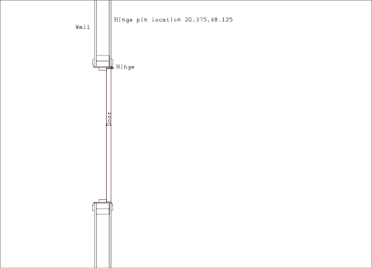
Now we will get a little more complicated with Figure 5.1. This is a drawing of a closet door. The dwg file is included with the download version of this manual. The file name is "MaxCAD_Manual_5-01.dwg".
Figure 5.1 Drawing of a closet door in a wall.
This figure has been reproduced with very fine lines. Start MaxCAD and load the file "MaxCAD_Manual_5-01.dwg".
- Select "Animated Rotation" from the "View" menu.
- Click one of the lines that make up the door. Both lines will turn gray.
- Optionally, hold the shift key and click the word "door".
- Click anywhere in the drawing board. You are going to override the mouse click for the center of rotation.
- Enter 1 in the "Angle Step (Degrees)" box.
- Press TAB and enter .1 in the "Time/Step (Seconds)" box.
- I'm sure you have noticed that these values are already in these boxes. Values from the previous usage of this feature are remembered.
- Check the box labeled "Override Center Point Mouse Click".
- In the "Center Point (X,Y) box type "20.375,48.125".
- Type "90" in the "Stop When Total Angle =" box.
- Click the "Go!" button.
You probably have noticed that I forgot to tell you to click on the part of the hinge that is mortised into the door. Click on the restore button near the upper left corner of the drawing board. If you are so inclined, repeat the steps above but this time select the part of the hinge that is supposed to rotate with the door.
You should have also noticed that the door did not catch on the frame as it opened. If you didn't, run the simulation again. You may want to set the stop angle to something less than 90 degrees so the time to completion will be shorter.
Now type Control O and load the file "MaxCAD_Manual_5-02.dwg".
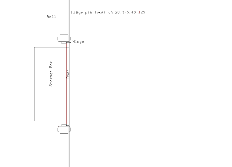
Figure 5.2 Drawing of a closet door with storage box installed.
This project is actually being seriously planned as an addition to my electronics shop which is in a spare bedroom of the house. The interior of the box will be accessed from the front through a door within a door. Details have been omitted to avoid a cluttered drawing. The point is to make sure the assembly can be opened without the box striking the door jam.Notice that the corner of the box passes through the frame. The vertical component of the distance from the corner of the box to the hinge pin is greatest when the corner is directly below the hinge pin. Play with the stop angle until the corner stops at this point. Decimal fractions of degrees are allowed.
- Select "Animated Rotation" from the "View" menu.
- Click on the door and the outline of the box.
- Optionally, click on the text.
- Click anywhere in the drawing board.
- The dialog will open and all values should be set from the previous run. They will be there even if you have turned off your computer since working with Figure 5.1.
- I recommend, as a time saver, changing the stop angle to 30 degrees.
- Click "GO!"
Lay a ruler on your computer screen and measure along the back line of the box. Decide how much needs to be cut off to clear the door jam. Draw in the new box before deleting the old one.
Start at the top right and draw to the top left, then down. Lay the ruler back on the screen and stop the vertical line short of the bottom line by the amount you measured above. Click and draw the line to the right until it hits the door. Make sure it is exactly horizontal and right click. Now delete the old box outline.
Now run the animation again and see if your adjustment gives the clearance you want. Remember this is wood work. Even if you measure 10 times the dimensions are never going to come out perfect. So leave a little extra clearance to allow for errors.
You could solve this problem with the original rotate function, infact I did before adding the code to make the animation happen. The problem is, to get the interfering objects exactly in the right place you have to fiddle the angle back and forth and by the time you get it there you don't know what the rotation angle is to get it back to the original position. Very little code was required to make this function. All I had to do was to call existing routines.
Back to Fun with Transistors.
Back to Fun with Tubes.
Back to Table of Contents.
Back to top.
5.2 Grid Spacing.
Type Control N or select "New" from the "Files" menu. You will see a black screen with green dots on it. These dots are the grid. They help the user to know if a line is parallel to the X or Y axis and quickly estimate distances.Back to Fun with Transistors.
- Press F5 or select "Grid Spacing" from the "View" menu.
- You will be prompted "Grid Spacing" at the top left of the drawing board. The blue box will display 0.4 and the characters will be selected.
- Type ".2" without the quotes then press the TAB key.
- Experiment with several different values.
Back to Fun with Tubes.
Back to Table of Contents.
Back to top.
5.3 Grid On/Off.
This function turns the grid on and off. The grid appears only on the screen and is not sent to the printer or to the HPGL plotter file.5.2.1 Using the Function Key F6.
- Press F6. Notice that the grid is no longer visible.
- Press F6 again. Now the grid is back.
5.2.2 Selecting from the menu.
Back to Fun with Transistors.
- Open the "View" menu. Notice that there is a check mark next to the "Grid On/Off" entry.
- Click on "Grid On/Off. The menu will close and the grid will disappear.
- Open the "View" menu again. Notice that the "Grid On/Off is not checked.
- Click on "Grid On/Off again.
Back to Fun with Tubes.
Back to Table of Contents.
Back to top.
5.4 Limits.
The limits set how much of the drawing board is covered by the grid. They also set how much of the drawing board is sent to the printer.5.3.1 Manually setting limits.
- Load the test drawing you used in Chapter 4.
- Press F7 or select "Limits" from the "View" menu.
- Type "-1,-1" without the quotes and press the TAB key.
- Type "1,1" without the quotes and press the TAB key. The Zoom has been set to 100 % for these limit settings.
- Press F3 6 times to zoom out until you can see the boarder. Notice that the grid only covers a small space around the origin.
- Leave the screen in exactly this condition for the next section.
5.3.2 Automatic Limit Settings.
Notice that the zoom has been readjusted to almost fill the screen and the grid now also fills the screen. Press F3 to zoom out to better see this.
- Press F7.
- Type the letter A, lower or upper case, in the box.
- Press the TAB key.
Now you can play with various limit settings both large and small to see how they work. After the limits have been set the screen is automatically zoomed to 100 percent for those limit settings.
5.3.3 One-to-one Scaling a Drawing to the Printer.
If you are making a printed circuit board or label for a control panel you need to know the scaling between the screen and printer page. Here's how.If the drawing is wider than it is high, do this.
If the drawing is taller than it is wide, do this.
- Set the limits for a total width of 10 and a total height of 7.5.
- Open the "Printer Setup" window and make sure the "Landscape Mode" box is checked.
- The drawing will print 1 to 1.
- Set the limits for a total width of 7.5 and a total height of 10.
- Open the "Printer Setup" window and make sure the "Landscape Mode" box is not checked.
- The drawing will print 1 to 1.
5.3.4 One-to-one Printing of larger drawings.
If part of the drawing is outside of the limit settings it will not be printed. Suppose you have a drawing which is 15 inches wide and 6 inches high. To print this drawing do this.Back to Fun with Transistors.
- Open the "Printer Setup" window and make sure the "Landscape Mode" box is checked.
- Set the limits to 7.5 inches high and 10 wide but make it the left most 10 inches of the drawing. The right most 5 inches will be outside the limits.
- Print the drawing.
- Change the limits to include the right most 10 inches of the drawing leaving the left 5 inches outside the limits.
- Print the drawing.
- Find the best place in the overlapping 5 inches to splice the pages together.
- Cut one page along this line and tape it to the other, uncut, page. If the drawing is a panel label carefully cut both pages along the chosen line, trim the top and bottom, and glue it to the panel.
Back to Fun with Tubes.
Back to Table of Contents.
Back to top.
5.5 Pan.
In some graphics programs the pan command will move the camera. That is if you pan to the left the objects on the drawing board will move to the right. I find this confusing.In this program the pan command moves the drawing board. If you pan to the left the objects will move to the left.
Back to Fun with Transistors.
- Press F2 or select "Pan" from the "View" menu.
- Left click near the origin.
- Stretch out the rubber band and right click near one corner of the screen. The origin will be moved to the position of the right click.
- Press F3 until you can see the whole drawing.
- Leave the screen in this condition for the next section.
Back to Fun with Tubes.
Back to Table of Contents.
Back to top.
5.6 Reset Zoom and Pan.
This function resets the Zoom to 100 % and centers the drawing limits in the screen window.Press F11 or select "Reset Zoom and Pan" from the "View" Menu.
That's all there is to it. It comes in handy if you have done a lot of zooming and panning. Try zooming in by pressing F4 until you can only see part of the drawing. Now experiment with panning around the screen. Then press F11 to quickly get back to 100 % zoom.
Back to Fun with Transistors.
Back to Fun with Tubes.
Back to Table of Contents.
Back to top.
5.7 Snap Width.
The snap width sets how far the MaxCAD cursor jumps with each snap.You will see that the dotted cursor can only be positioned on the green dots which are 0.4 inches apart. The small solid cross is generated by Windows and apparently cannot be turned off. I would if I could find a way. The larger dotted cross is generated by MaxCAD and is the actual working cursor. Mouse clicks are registered on the snap positions. Play with different values of Snap Width.
- Type Control N.
- Press F8 or select "Snap Width" from the "View" menu.
- Type .4 into the box and press the TAB key.
Back to Fun with Transistors.
Back to Fun with Tubes.
Back to Table of Contents.
Back to top.
5.8 Non-orthogonal Snap.
Press F8 and type ".2,.4" without the quotes and press the TAB key.As you move the mouse you will see that the cursor jumps 0.2 inches in the X direction but 0.4 inches in the Y direction. This comes in handy if you need to snap fractional inches in one axis and decimal values in the other. I have run into this situation when designing a bookcase.
If you type a single number without a comma the program will assume you meant to type the same number for both axes. When you press F8 again you will see that X snap and Y snap have been set equal.
Back to Fun with Transistors.
Back to Fun with Tubes.
Back to Table of Contents.
Back to top.
5.9 Snap Mode.
It will appear as if this is somewhat redundant. Well, it is. The Snap Mode routine was written first. Non-orthogonal Snap was added later. It was decided to leave Snap Mode in place to avoid any compatibility problems.There are 4 snap modes. They are;
- Off,
- X axis only,
- Y axis only,
- Both axes.
5.8.1 Changing Snap Mode Using the Menu.
Note. The menu shows the current setting of the snap mode. When you select it the mode advances to the next setting but the menu closes so you can't see the change take place. That's why it's displayed on the screen.
- Type Control N to obtain a blank screen.
- Press F8 and type .4 in the box and press the TAB key.
- Open the "View" menu.
- You will see "Snap Mode (Both)"
- Select this menu item. The words "Snap (Off)" will show in the upper right corner of the drawing board.
- Move the mouse around. You will notice that the dotted cross follows the solid cross smoothly in both axes.
- Once again open the "View" menu and select the item "Snap Mode (Off)"
- The legend at the upper right will change to "Snap (X)".
- Move the mouse and notice that the dotted cross follows the solid one smoothly in the Y direction but jumps, (snaps), in X.
- Open the "View" menu and select the item "Snap Mode (X)".
- The legend at the upper right will change to "Snap (Y)".
- Move the mouse and notice that the dotted cross follows the solid one smoothly in the X direction but jumps, (snaps), in Y.
- Open the "View" menu and select the item "Snap Mode (Y)".
- The legend at the upper right will change to "Snap (Both)".
- Move the mouse and notice that the dotted cross jumps, (snaps), in both X and Y.
- Leave everything in this state for the following section.
5.8.2 Changing Snap Mode Using the Function Key F9.
It is assumed that you have just finished the steps in section 5.8.1.If you didn't notice it before, pay attention to the mouse cursor position legend just in front of the word "Snap". Repeat steps 1 through 8 above and notice that the number of decimal places in the position display changes. Set the "Snap Width" to 0.25 and note how the position coordinates are displayed. No more decimal places are shown than required to fully characterize the cursor position.
- Press the F9 key and note that the legend in the upper right of the drawing board changes to "Snap (Off)"
- Move the mouse and note that the dotted cursor moves smoothly.
- Press the F9 key and note that the legend in the upper right of the drawing board changes to "Snap (X)"
- Move the mouse and note that the dotted cursor moves smoothly in Y but snaps in X.
- Press the F9 key and note that the legend in the upper right of the drawing board changes to "Snap (Y)"
- Move the mouse and note that the dotted cursor moves smoothly in X but snaps in Y.
- Press the F9 key and note that the legend in the upper right of the drawing board changes to "Snap (Both)"
- Move the mouse and note that the dotted cursor snaps in X and Y.
5.8.3 Changing Snap Mode on the Fly.
The F9 key may be used to change snap mode even in the middle of a draw command. The following example may seem a little artificial but It is likely to happen to you eventually. The snap values have been made atypically large to make the steps easier to perform.The corner formed by the two lines is as perfect as if it had been drawn with snap on. If you zoom in to 800 percent you will see that neither the corner nor the arc hitting the line are as perfect as they first appeared. When performing operations of this sort it is a good idea to zoom in as far as possible before performing the steps. You may not change the zoom setting in the middle of a draw command.
- Press F8 and set the snap width to 0.2.
- Type L and draw a line from the point 0,-0.2 to 1,-0.2.
- Press the mouse wheel and draw another line from 0.8,0.8 to 1.6,1.2.
- Type A1, the A first then the 1, and place the center point at 0,0.
- Move the mouse to the point 1.4,0. A dotted circle will pass through the mouse cursor.
- Left click and move the mouse up. You want to make the end of the arc hit the line that is at an angle. Even moving the mouse farther away from the center still won't allow you to make the rubber band cross the dotted circle on the diagonal line.
- Press F9 once and note that "Snap (Both)" is now displayed at the top of the screen.
- Move the mouse until the rubber band crosses the dotted circle exactly on the diagonal line. Moving the mouse far away from the center point (0,0) will make this easier. Remember, you don't have to be on the dotted circle when you click the third point.
- When you are satisfied, right click and the arc will terminate exactly on the diagonal line.
- Press F9 three times to bring the snap mode back to "Both".
- Press F8 and set the snap width to 0.4.
- Type L and start a line at 0,-1.2.
- Now, you want to draw the line to the end of the horizontal line. But you can't get there from here. You don't want the line to stop short of the line or go past it.
- Press F9 twice and "Snap (X)" should show at the top of the screen.
- Now you note that you can move the cursor smoothly in Y but only in 0.4 inch steps in X.
- Set the cursor on the end of the line. This is easy because it is obvious when the dots of the cursor are on the solid line. Right click.
Back to Fun with Transistors.
Back to Fun with Tubes.
Back to Table of Contents.
Back to top.
5.10 What Is It?
No, I'm not asking you, that's what you can ask MaxCAD. This command may be of more use to me than it is to you but it's there if you ever need it, or are curious. It probably gives you more information than you would ever want to know.Back to Fun with Transistors.
- Load your practice drawing if it is not presently loaded.
- Type Control J or select "What is it" from the "View" menu.
- Select one, and only one, object on the drawing board.
- Press the TAB key to select the answer of Y for yes.
- A blue screen will come up with the information about the object printed in it.
- When you are finished studying the information click on the "Close" button at the top of the drawing board.
Back to Fun with Tubes.
Back to Table of Contents.
Back to top.
5.11 Zooming.
Selecting "Zoom In" from the "View" menu or pressing F4 will zoom in on the drawing about 25 % each time the menu item is selected or the F4 key is pressed.Selecting "Zoom Out" from the "View" menu or pressing F3 will zoom out from the drawing about 25 % each time the menu item is selected or the F3 key is pressed.
Zoom in is limited to 800 % and zoom out is limited to 0.01 %.
If you made your practice drawing exactly like mine there is a place where an arc goes past the angle a little so the line which was supposed to meet the end of the arc, hits it at a tangent. If you don't have such an item in your practice drawing, add one to it. Let's practice zooming and panning.
You can now see the details of where the arc ends and How the line actually hits the arc. On my screen it looks like this.
- Press F2 and left click on the arc overlap described above.
- Move the mouse to the origin, (0,0), and right click.
- The arc overlap will move to this point.
- Press F4 until the screen will no longer change. The zoom factor will be 800 %.

Figure 5.3 Screen shot of zoomed in drawing.
Back to Fun with Transistors.
Back to Fun with Tubes.
Back to Table of Contents.
Back to top.