At this point I assume you have spent the bucks and have all the parts in hand. I will give fairly detailed instructions because I suspect that many people may want to duplicate this project.Switch Subassemblies.
In the instructions below you are directed to use 20 gauge wire. This is not for current carrying capacity, it is for physical strength. Even so I wouldn't recommend sending it up in the space shuttle, I wouldn't even ship it by one of the well known package shipping companies.Prepare 54 1 k ohm 10 watt resistors as follows.
- Cut 54 lengths of number 20 gauge solid hookup wire to 2-1/2 inches. Then remove 3/16 of insulation from each end.
- Cut one resistor lead to 1/4 inch.
- Cut the other lead to 3/4 inch.
- bend a hook in the short lead of the resistor and a hook in one end of the wire prepared above.
- Hook them together and squeeze them shut with needle nose pliers.
- Solder the connection.
- Hold the resistor up with the soldered on wire up and the righting on the resistor toward you.
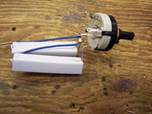
- Bend the bottom lead (3/4 inch long) away from you until it is at right angles to the resistor body as shown in the photo.

- Bend the top lead (soldered on wire) to the left and down until it nearly touches the bottom lead as shown.
Prepare 6 switches as follows.
- Temperarily install a knob on one of the switches to make it easier to turn.
- Count the clicks to see if it is set for 11 positions. Don't forget to count the end position, a common mistake. My switches came set to 11 positions.
- If it is not set to 11 positions remove the nut and lock washer from the mounting bushing. Lift up the little metal ring and move it to the 11 position. Some trial and error may be required to find it.
- Use an ohmmeter or continuity tester to determine which outer lug is never connected to the one inside the outer ring of lugs. (Position number 12)
- Cut off the lug in the outer ring which is never connected.
- Set the switch fully clockwise (to the right) as viewed from the front (knob) end
- Use the ohmmeter again to identify the outer lug that is connected to the inner one.
- Cut off the outer lug.
- You now have a gap of two adjacent lugs in the outer ring as shown in the photo below.
- Hold the switch with the lugs toward you and the gap at the bottom.
- The lug to the left of the gap is number 1.
- The lugs are numbered clockwise from the gap, 1, 2, 3, etc.
- Connect the ū inch lead of one of the resistors prepared earlier to lug 1 (S1) and the long insulated wire from the other end to lug 2 (NS).
- Make mechanically strong connections by crimping the wire half way around the lug after passing the end through the hole.
- The symbol (S1) means solder one wire in the lug.
- The symbol (NS) means no solder, don't solder yet.
- Position the resistor Parallel to the switch shaft as shown in the photo.
- Connect the short lead of another resistor to lug 2 (S2) and the long lead to lug 3 (NS)
- Continue in a similar manner around the switch.
DO NOT SOLDER LUG 10.Prepare 6 more switches by cutting off the lugs as described above.
Prepare 27 3 k ohm 5 watt resistors as follows.
- Cut one lead to ū inch.
- Leave the other lead full length.
- Bend the leads in the same manner as the 10 watt resistors.
Prepare 3 switches as follows.
Connect and solder nine 3 k ohm 5 watt resistors to each of 3 switches as you did above. Remember not to solder lug 10.
Prepare 27 10 k ohm 1 watt resistors as follows
- Cut one lead to 5/8 inch.
- Leave the other lead full length.
- Bend the leads in the same manner as the 10 watt resistors.
Connect and solder nine 10 k ohm 1 watt resistors to each of 3 switches as you did above. Remember not to solder lug 10.
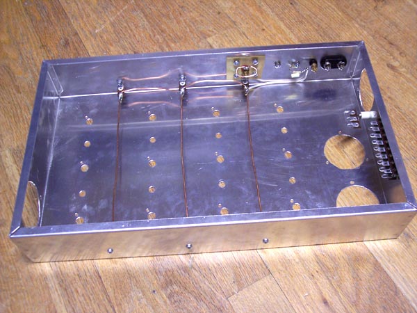
The Chassis.
The enclosure used is a 17 x 10 x 3 inch aluminum chassis with bottom cover. A drilling template is shown below. Print it out, scale it to size (see below) and stick it to the chassis with double sided scotch tape. Mark the center of each hole with a center punch. Enlarge the marks made by the punch by holding a 5/64 drill bit between your fingers and rotating it while holding it on the mark. Then drill out the holes to the proper size.The switch holes are 5/8 inch in diameter and the locking studs are 9/64 inch. The overload lamp holes depend on what kind of lamp holders you have decided to use. See parts list. The mounting holes for the meter are 1/8 inch.
I don't think there is any way I can set the scale so you can just print it out and use it. You will have to load it into a graphics program and scale it to fit. Unless you have an oversized printer, I don't, you will have to break the diagram into three pieces and print them out separately. To help you scale, the center to center distance between switches is 3-1/2 inches horizontally and 3 inches vertically.
The two large circles on the left are the meters. If you are not going to install them or if you have meters of a different size you will need to redraw that part of the drawing. The switches were drawn with the resistors showing to indicate any interference problems. Just ignore them. The little hole that is indicated on the right side of the large meter cutout will be explained when discussing the fan cutout below.
The switches are entirely made of plastic, except for the contacts of course. You could not tighten the nut tight enough, without stripping the threads, to hold the switch from turning. You MUST drill the hole for the locking stud to be inserted into.
As said elsewhere the fan is absolutely necessary. All that heat from all those resistors has to be removed or the whole thing would overheat and you would wind up with a box full of burned out resistors. Here is the drilling template for the fan. The diameter of the large circle is 2-9/32 inches.
There are two copies so you only need to use one piece of paper. Cut them out and stick one on each end of the chassis, one near the upper left corner and the other near the lower right corner. The rectangle on the front template shows where the fan goes. The other hole is for the air to get out.
The small hole at the right is a starter hole for cutting out the large hole. I did it with the circle cutter attachment of a Dremel tool. Here's how.
- Drill at the center mark of the large hole and the starter hole at the right with a 1/8 inch drill.
- Slightly ream out the center hole by moving the back end of your electric drill in a circle while the motor is running and the bit is in the hole. Don't get carried away, just a little. The purpose of this is so the metric sized center locator of the Dremel circle cutter will fit through the hole.
- Cut a piece of wood such as a 1 x 2 to about 9 inches so it will fit inside the chassis.
- Clamp the wood in place behind where the fan cutout is to be. Be sure to position the clamps so you can turn the circle cutter all the way around.
- The purpose of the wood is to maintain guidance at the end when the piece which is being cut out no longer has a substantial connection to the rest of the chassis.
- At the center mark of the large hole and the starter hole drill into the wood with the 1/8 inch bit. DO NOT REAM OUT EITHER HOLE.
- Take the center locator out of the Dremel circle cutter and tap it into the wood at the center hole with a small hammer, or a light touch on a big one.
- Reassemble the circle cutter but leave the radius setting loose so you can move it back and forth.
- Install the 1/8 inch router bit in the Dremel tool and install the tool on the circle cutter.
- adjust the cutting depth, length of the bit that extends below the circle guide, so it will cut through the aluminum chassis but NOT all the way through the wood.
- Install a pair of ear protectors over your ears.
- Insert the center locator into the center hole and slide the radius back and forth until you can insert the bit into the starter hole.
- With the circle cutter flat against the chassis's surface firmly tighten the radius lock.
- Turn on the Dremel tool and set the speed to 6. Start moving the cutting guide slowly around the circle.
- I go clockwise but I don't think it makes any difference. WHAT EVER YOU DO DON'T BACK UP. CONTINUE AROUND THE CIRCLE ALWAYS IN THE SAME DIRRECTION.
- Use a small round or rounded file to remove the rough edges from the hole.
The hot input binding post should have extra insulation from the chassis. Here is how to do that.
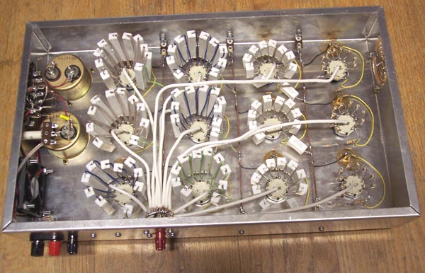
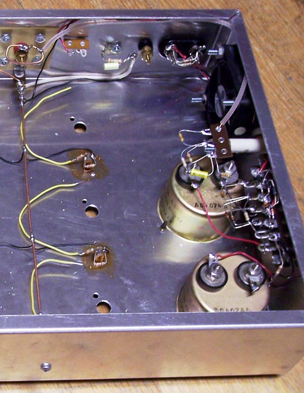
As shown in the photo mount six 1 lug terminal strips inside the long sides of the chassis exactly centered between the columns of switches. These are to hold the common connecting wires.
- Obtain a 2 inch square piece of insulating material such as the glass-epoxy or fiber glass from circuit board material with the copper removed.
- Drill a hole exactly in the center and mount a red binding post.
- On the back of the chassis, exactly between the first two columns of switches, and centered from top to bottom, make a hole ū inch in diameter. You may have to use the Dremel circle cutter for that.
- Drill four 9/64 inch holes in a square around the ū inch hole in the chassis. The holes should be at the corners of a 1 inch square.
- Place the insulating board inside the chassis with the binding post centered in the ū inch hole. Clamp it in place and drill the 9/64 inch holes through the insulating material. You may want to use this method.
- Clamp the insulating board at two corners. They don't have to be opposite corners.
- Drill one hole while supporting the board from inside the chassis. Be careful not to drill your finger.
- Place a 6-32 screw through the hole and put a lock washer and nut on it. Tighten it down.
- Similarly drill the remaining accessible corner and install a screw, lock washer, and nut.
- Remove one of the clamps and drill and install a screw, lock washer, and nut.
- Remove the remaining clamp, drill, and install a screw, lock washer, and nut.
In the discussion below the top of the chassis is the side which is down in the photo. You can see the H Load binding post mounted on a piece of fiber glass board. There is a solder lug on the binding post and a piece of number 14 bare copper wire formed into a loop and soldered in place. The C Load binding post is to the right and a piece of insulated wire connects from this post to the bare copper wires that will be the common connections, not connected to the chassis at any point. Just to the left of the C Load post is a grounding lug and the 100 k ohm resistor and .001 microfarad capacitor that connect between them can be seen. The screw between the H Load terminal and the ground lug will be used to mount a 1 lug terminal strip that will hold the other end of the 750 ohm 10 watt resistor from lug 10 of S1. To the right of the C Load binding post are the two posts for the milliammeter.
The cutout for the fan is on the right in the picture and the air outlet cutout is on the left.
The two large holes in the chassis top are for the analog meters that serve as the voltmeter and milliammeter.
There are two 8 lug terminal strips mounted with common screws. They are for the circuitry of the ammeter, voltmeter, and fan voltage regulator and bridge. The three lug terminal strip is mounted on a 1 inch ceramic standoff insulator. These lugs are for two of the three 3.3 meg ohm resistors that are in the voltmeter circuit. These resistors may be at potentials of 1000 and 666 volts. Mount these terminal strips low enough to avoid interfering with the meters.
Six 1 lug terminal strips are mounted, three on the back, and three on the front, near the top of the chassis. The mounting screws can be seen on the front. These lugs are mounted half way between the columns of switches.
Install all of these things on the chassis.
The Meter Scales.
There are three basic ways to deal with the question of making new scales for the meters. One is to just leave them as they are and do the simple math in your head to interpret the reading. That's pretty simple for the 1000 volt scale but could get a little tricky for the 800 milliamp scale. Making new scales will give your project a professional look.Second is to take out the original scale, scan it, and use a graphics program to redraw it. For the 1000 volt meter all you need to do is change the numbers from 20 to 200, 40 to 400, etc, and the word "MICROAMPERES" to "VOLTS". Then print out the graphic, cut it down to size and glue it over the back side of the original scale face. Place a piece of dark paper behind the original face when you scan it so the edges and mounting holes will be readily apparent on the reprinted graphic. The 800 mA scale might not be as easy. The spacing between, and number of, scale markings will have to be changed. Of course you could always make it 1000 mA (1 amp) so only the numbers would have to be changed. If you plan to use the "scan and print" method, I would say definitely change the current meter to 1000 mA full scale.
The third way is to use the drawings I will provide or use a CAD program you are familiar with to draw new scales. Which ever way you do it I suggest you print out a trial version on tracing paper and lay it over the original face to get the scaling right.
Most likely the meters you will find will not be the same size as mine. Here are my meter scales. Maybe they will be a starting point if nothing else.

The circles are the mounting holes for the meter face. It is unlikely they will be in the exact same position relative to the rest of the scale in your meters.Wiring the meters.
Cut the ground lugs off of the two 8 lug terminal strips. This should reduce the possibility of a wiring error. DO NOT CUT OFF THE GROUND LUG OF THE 3 LUG STRIP MOUNTED ON THE CERAMIC INSULATOR.The milliammeter is the one closest to the front of the chassis. The lug closest to the front on the strip closest to the bottom of the chassis is the one that holds one end of the 1 k ohm resistor in the milliammeter circuit. See the photo below.
- Install four 1 ohm ž watt resistors across the two ammeter binding posts (NS) and (NS).
- Measure off the length of a red and black wire to run from the binding posts to the meter lugs. Route the wires along the chassis so they will not get caught in the fan. Twist them together.
- At the binding post end connect the red wire to the red binding post, (S5) and the black wire to the black post (S5).
- Connect the red wire to the positive terminal of the meter, (Right lug as viewed from the front of the meter), (S1).
- Connect the black wire to the terminal strip lug closest to the front of the chassis and farthest from its top, (NS).
- Connect a 1 k ohm resistor between the lug holding the black wire and the other lug of the meter. Don't wrap the ends of the wire around the lugs but just hook them over the lugs so they can be changed easily if necessary. Solder both connections.
Ammeter calibration.
This metering circuit is very familiar to me because I taught it for 33 years. The point that was most difficult to get across was the distinction between the meter movement and the meter circuit. The meter movement is the round thing you can hold in your hand. The meter circuit is the meter plus all of the resistors. In a teaching lab sometimes I would let them make mistakes with the hope they would learn from them. I had worked out the resistor values so if they confused the distinction they wouldn't burn out a meter movement, they would just get the wrong numbers for the measurement.Here we have no such luxury. If you make the wrong connection in the following steps you will, not may but will, blow out the meter. If you have followed the steps above, you have two binding posts on the back of the chassis which connect to the meter circuit. So
Turn the chassis right side up on your workbench. Make connections ONLY to the binding post on the back of the chassis. DO NOT EVER, EVER, NEVER, make a connection to anything under the chassis. CLEAR?
Dust off your old transistor power supply. Locate a resistor that when connected across it will cause 500 to 800 mA to flow. For example, if your power supply has a maximum voltage of 20 volts and a maximum current of 500 mA locate a resistor that is 20 v / 0.5 A = 40 ohms. The wattage rating must be, in this example, 20 v times 0.5 A = 10 watts. Connect up the following circuit.
For a verbal description Click here.
Set the DMM to measure DC amperes and the 2 amp range. Set the power supply voltage to minimum. While watching the meter in the load box turn on the power supply. If the meter does not slam against the stop, increase the voltage. You should get a reading. If the meter pins or doesn't move at all check the wiring carefully.Turn off the power and make sure the meter is mechanically zeroed. If it is not, use a small screw driver to adjust the pointer to zero. Now turn the power supply back on and adjust its voltage until the digital meter reads some convenient value such as .500 amps.
Look at the reading on the analog meter. If it is right on, congratulations. If it is low you need to decrease the value of the 1 k ohm resistor. If it is high, you need to increase the resistor. I am assuming you have 5% values around 1 k ohm. That is 820, 910, 1.0 k, 1.1 k, and 1.2 k ohm. If the correct value seems to fall between two values install the higher value. Then locate a resistor which is approximately 20 times the installed value. Connect this resistor in parallel with the installed resistor.
Voltmeter Wiring.
When bending the leads on diodes do not just grasp the diode in your fingers and bend the lead. You stand a good chance of breaking the glass or plastic body of the diode. Instead hold the lead with a pair of needle nose pliers next to the diode body and apply bending force to the end of the lead away from the diode.If you happen to have a printed circuit lead bender use the .4 spacing to go between adjacent lugs of a terminal strip and the .75 spacing to connect to one, skip one and go to the next.
Wire the voltmeter circuit on the terminal strip which is closest to the top of the chassis. That's the one which is farthest away from you as you look into the chassis. The two lugs on the left will not be used. The next four left to right are the 4 terminals of the diode bridge as follows; Input, negative output, positive output, input.
- Connect a length of black wire from the negative output lug (NS) to the negative terminal of the meter to be used as the voltmeter (S1).
- Connect another length of black wire from the left hand input terminal of the bridge (NS) to the common (bear copper) wire (S1). Route this wire around the edge of the chassis making sure it will not interfere with later mounting of switches or get caught in the fan.
- Obtain some old TV coaxial cable and remove the outer insulation and shield. You may find that the center conductor and its insulation will come out once you get it started. This is the part you want.
- Route the coax center conductor from the copper wire loop on the load H terminal (S1) along the edge of the chassis to the right hand lug on the 3 lug terminal strip (NS) which is mounted on the insulator.
- For the moment leave the leads of the 1N4148 diodes full length. Bend the leads, as described above, on two of them to be connected between adjacent lugs on the terminal strip.
- Bend the leads on two others to be connected between two lugs with one in between.
- The leads on the ones for adjacent lugs will extend farther from the side of the diode body than the others. Cut these off to be the same length.
- Hold one of the adjacent lug diodes with the cathode to the left and bend hooks downward in the ends of the leads.
- Hook the leads over the right input and the positive output of the bridge.
- Do not wrap the leads around the lugs. Squeeze the hooks shut over the ends of the lugs. (NS) (NS)
- Take one of the wide spaced diodes and hold it with the cathode to the right. Bend hooks downward in the ends of the leads
- Connect this diode from the left input (NS) to the positive output (NS).
- Hold the other adjacent lug diode with the cathode to the left and bend hooks downward.
- Connect this diode from the left input (S3) to the negative input (NS).
- Hold the last, wide spacing, diode with the cathode to the right and bend hooks as above.
- connect this diode between the right input (S3) and the negative output (S3).
- bend the diodes slightly apart vertically so the leads don't touch. There is no high voltage in this part of the circuit that can arc across a small gap.
- Connect a 750 k ohm resistor from the positive terminal of the meter (S1) to the positive output of the bridge (S3).
- In the photo above this resistor goes from the bridge to one of the unused lugs on the terminal strip and a red wire goes from there to the meter movement. Do it however you like.
- connect a 3.0 meg ohm resistor from the right hand lug of the 3 lug strip (S2) to the center lug (NS). Leave the leads full length and hook them over the ends of the lugs as you did with the diodes.
- Connect a 3.3 meg ohm resistor from the center lug (S2) to the left lug (NS). Do not fill the lug opening with solder.
- Connect a 3.0 meg ohm resistor from the left lug on the 3 lug strip (S2) to the right input of the bridge (S3). Do not fill the lug opening on the 3 lug strip with solder.
Voltmeter Calibration, DC.
Connect an adjustable power supply that will go up to 400 or 500 volts to the H and C load binding posts. Turn it up slowly to be sure the meter isn't going to slam.Also set your DMM to measure 1000 volts DC and connect it to the power supply. Set the supply voltage to 500 volts by the DMM and read the voltmeter. If it reads high turn off the power supply and change one or both 3.0 meg resistors to 3.3 meg. If it reads low change the 3.3 meg to a 3.0 meg. If it still reads low change one or more resistors to 2.7 meg.
Voltmeter Calibration, AC.
Turn off the power. Temporarily solder one end of a 7.5 meg ohm resistor to one end of a .0033 microfarad 650 volt capacitor. Temporarily solder the free capacitor lead to the left lug of the 3 lug strip. Temporarily solder the free end of the resistor to the center lug of the 3 lug strip.Turn the chassis over and connect the load H and C terminals to an adjustable source of AC voltage that will go above 500 volts. This could be a power transformer plugged into a Variac. Set your DMM to the 750 volt Ac range and also connect it to the H and C terminals.
Turn on the power and adjust the voltage to 500 volts by the DMM. If the meter in the load box reads 500 volts skip down to final voltmeter wiring.
If the meter reads low, drop the 7.5 meg ohm resistor down to 6.8 meg or 6.2 meg. If it reads high, increase the 7.5 meg to 8.2 or 9.1 meg. Change the resistor until the meter reads right.
Final Voltmeter wiring.
Turn off all power and disconnect all leads. Turn the chassis over and unsolder the temporary resistor and capacitor. Cut one lead of each to ― inch. Bend hooks in the end of each, hook them together and solder them together. Leave the other lead of the resistor full length. Permanently solder the free end of the resistor to the center lug of the 3 lug strip. Permanently solder the free end of the capacitor to the left lug of the 3 lug strip. Shorten this lead to bring the capacitor approximately parallel to the resistor that goes from the left lug of the 3 lug strip to the diode bridge as shown in the photo above. Position all resistors so they aren't touching.Fan Wiring.
wire another bridge using 1N4002 diodes on the other terminal strip exactly parallel to the one for the meter. Shorten up the leads on these diodes and position them toward the end of the chassis instead of out away from it as before. Do not hook the diode leads over the lugs but pass the ends through the openings and wrap them around in the conventional manner.Mount a 2 lug terminal strip, 1 ground and 1 insulated on the screw between the H load terminal and the chassis grounding lug on the back of the chassis. Cut off the ground lug.
Measure off two lengths of hookup wire, one red and one black, to run between the diode bridge and; red wire to terminal strip just installed, and black to the common wire.
Twist the wires together. They are of different lengths, line up the ends at one end.
At the even end connect the red wire to the right bridge input, (S3), and the black wire to the left bridge input, (S3).
At the uneven end connect the red wire to the newly installed terminal strip, (NS), and the black wire to the common wire, (S1).
Connect the cathode of one of the zener diodes, 1N4742A, to the positive output of the bridge, (NS) and the anode end to one of the unused lugs to the left, (NS)
Connect the other 1N4742A diodes cathode to the terminal where you connected the anode of the other one, (S2) and the anode to the negative bridge output, (NS).
Mount the fan on the inside of the chassis near the terminal strips and meters, and the fan guard on the outside using 8-32 x 1-1/4 inch machine screws with lockwashers and nuts on the inside. Position the fan with the label facing the inside of the chassis. Mount the other fan guard over the cutout on the other end of the chassis with 8-32 x 1/4 inch screws with lockwashers and nuts on the inside.
The fan has a small plug on the end of its wires. Cut off the plug and discard it. Cut the Yellow wire off short at the fan, it will not be used. The red and black wires go to the bridge so cut them to length, strip ž inch of insulation, twist the fine strands together and melt a small amount of solder on the bare wire to hold the strands together.
Connect the black wire to the bridge negative, (S4) and the red wire to the positive bridge output, (S4).
Testing the Fan.
For this test you need a power supply capable of delivering 100 volts at 100 ma. Temporarily solder one lead of a 750 ohm 10 watt resistor to the newly installed terminal strip where the red wire comes. Use alligator clip leads to connect the output of the power supply to the free end of the 750 ohm resistor and the common wires.When you turn on the power supply and bring its voltage up to 100 volts the fan should run blowing air into the chassis. Turn off the power, reverse the leads, and turn it back on. The fan should run in the same direction.
Overload Lamp Wiring.
- Turn the chassis upside down and place it with the back, side with the binding posts, toward you.
- Cut twelve 4-3/4 inch lengths of yellow number 22 insulated solid hookup wire.
- Install twelve 62 k ohm ž watt resistors, one on each lamp. One lead to one terminal and the other lead to the other terminal. The resistor should extend out away from you. Exactly how you do this will depend on what kind of lamps or lamp holders you have. Do not solder either connection.
- In this step you will connect a length of black hookup wire, not one previously prepared, between the lamp and the common wires. In my case the lamp terminals are rather fragile. The specific instructions are designed to minimize the stress on the terminals.
- Connect the wire to the nearest common wire. (S1).
- Route the wire down against the chassis and where it will not interfere with the switch. Adjust the length to connect to the left terminal of the lamp. Strip the end and connect it to the left terminal. (S2).
- Cut the leads on twelve 39 k ohm resistors to a length of 3/8 inch.
- Connect the twelve resistors and twelve yellow wires, prepared earlier, as follows.
- Remove 3/8 inch of insulation from one end of a wire. Bend a hook in the end of the wire and one resistor lead.
- Hook the ends together, squeeze the hooks shut and solder the connection.
- Remove ž inch of insulation from the other end of the wire.
- Connect the other resistor lead to the right hand lug of a lamp. (S2).
- Rout the lead to the right, around where the switch will be and against the chassis as shown in the photo above. It will be connected later.
Installing the Switch Subassemblies.
Carefully inspect each of the twelve switches to make sure that all lugs, except number 10, are soldered, that there are no shorts, and no wiring errors.After you remove the nut and lockwasher from the switch there is another metal washer still on the switch. This is the stop adjustment. Be sure it does not come off.
WARNING! WARNING! When starting the nuts on the plastic switches be very, very careful not to cross thread them. Once you have started a nut cross threaded it cuts new threads and it is EXTREMELY difficult to get it to go right again.The chassis should still be positioned upside down and with the back toward you.
- Locate one of the switches with 10 k ohm 1 watt resistors installed on it.
- Connect one lead of a 10 k ohm 1 watt resistor to lug 10 of the switch. (S2). I could only fit two wires through a switch lug. Let the resistor lead come radially outward for some distance and then bend it to the left.
- Cut the remaining lead of the 10 k 1 watt resistor to about half its length. Cut one lead of a 1 k ohm ž watt resistor to about half its length. Bend hooks in the end of each lead, hook them together, squeeze the hooks shut and solder.
- Install the switch in the hole in the upper right corner. Make sure the locking stud drops into the hole and the wire from the overload lamp is not pinched between switch and chassis.
- Reinstall the lockwasher and nut. DO NOT OVERTIGHTEN THE NUT!
- Bend the free lead of the 1 k ž watt resistor around the common wire and cut off excess lead length. (S1). Position the resistors and their leads away from the switch, resistors and the overload lamp.
- Bend a hook in the end of the wire coming from the lamp which is behind the switch, hook it over the resistor lead coming from lug 10 of the switch and squeeze the hook shut. (S1).
Follow the same steps to install another switch with 10 k ohm 1 watt resistors in the middle-right hole.
Follow the same steps to install another switch with 10 k ohm 1 watt resistors in the lower-right hole.
- Locate one of the switches with 3 k ohm 5 watt resistors installed on it.
- Cut one lead of a 3 k ohm 5 watt resistor to ū inch. Connect this lead to lug 10 of the switch. (S2). Let the resistor and lead come radially outward from the switch.
- Install the switch in the hole in the second from the right and upper hole. Make sure the locking stud drops into the hole and the wire from the overload lamp is not pinched between switch and chassis.
- Reinstall the lockwasher and nut. DO NOT OVERTIGHTEN THE NUT!
- Bend the free lead of the 3 k 5 watt resistor around the common wire to the right of the switch and cut off excess lead length. (S1). Position the resistor and its leads so they don't touch the other resistors on the switch and are well away from the resistors on the next switch to be installed.
- Bend a hook in the end of the wire coming from the lamp which is behind the switch, hook it over the resistor lead coming from lug 10 of the switch and squeeze the hook shut. (S1).
In a similar manner install another 3 k ohm switch in the middle hole in the second from the right column.
In not quite the same way install another 3 k ohm switch in the bottom hole. The 3 k ohm 5 watt resistor from lug 10 needs to be routed upward from the switch and the lead bent downward to connect to the common wire that runs along the front of the chassis.
Now you will install the 6 switches with 1 k ohm resistors mounted on them. Work from top to bottom and right to left. The last switch to be installed should be the lower left corner. Follow this procedure.
- Locate one of the switches with 1 k ohm 10 watt resistors installed on it.
- Cut one lead of a 1 k ohm 10 watt resistor to ū inch. And the other lead to ž inch.
- Connect the ū inch lead to lug 10 of the switch. (S2). Position this resistor parallel to all the others on the switch.
- Install the switch in the third from the right and upper hole. Make sure the locking stud drops into the hole and the wire from the overload lamp is not pinched between switch and chassis.
- Reinstall the lockwasher and nut. DO NOT OVERTIGHTEN THE NUT!
- Cut a 2-3/4 length of number 20 insulated hookup wire, remove the insulation from both ends, bend a hook in one end and a hook in the short resistor lead. Hook the leads together, squeeze the hooks shut and solder.
- Bend the lead down to the common wire. Bend the end around the wire to the right of the switch and cut off excess lead length. (S1).
- Bend a hook in the end of the wire coming from the lamp which is behind the switch, hook it over the resistor lead coming from lug 10 of the switch and squeeze the hook shut. (S1).
Follow the same procedure for four more switches. The procedure for the last switch is slightly different.
- Locate the last switch with 1 k ohm 10 watt resistors installed on it.
- Cut one lead of a 750 ohm 10 watt resistor to ū inch. Leave the other lead full length.
- Connect the short lead to lug 10 of the switch. (S2). Position this resistor parallel to all the others on the switch.
- Install the switch in the lower-left hole. Make sure the locking stud drops into the hole and the wire from the overload lamp is not pinched between switch and chassis.
- Reinstall the lockwasher and nut. DO NOT OVERTIGHTEN THE NUT!
- Bend a hook in the end of the wire coming from the lamp which is behind the switch, hook it over the resistor lead coming from lug 10 of the switch and squeeze the hook shut. (S1).
- Connect the free end of the 750 ohm resistor to the one lug terminal strip which is mounted between the H load binding post and the chassis grounding lug. You may have to loosen the screw and rotate the strip slightly so the wire will reach.
Final Wiring.
For this part of the wiring you need wire which will withstand higher voltage than the average hookup wire. You can buy high voltage wire if you want to or you can use the inner conductor and its insulation from old TV coaxial cable.To recover wire from coax cut off about two feet and at one end strip a couple of inches of outer insulation, foil shield, and drain wires. Clamp the inner wire and insulation in a small vice and pull the outer part off. Cut off and discard the part where the vice crushed the insulation.
Do not place a bend in the wire near the connection being soldered. The insulation wants to be straight. The heat from soldering will soften the insulation enough for the wire to break through the side. The insulation will straighten out leaving the bent part of the wire bare. Form the wire into the shape you want after everything has cooled off.
Connect the lug of each switch that is inside the circle and not yet used, to the copper wire on the H load binding post. The order doesn't matter much. For ease of wiring be sure you don't run a wire over a switch that has not been connected.
This completes the wiring instructions. I don't quite know why I went into such detail. I guess I wanted to see if I could actually write a Heathkit manual. I doubt if I will ever do it again.
Here is the label for the front panel. You will have to scale it the same as you did the drilling template. It looks pretty bad on screen but it will download to a file at high resolution and permit you to rotate, trim, and print it out so it will look good.
- Introduction.
- Schematic and circuit description.
- Construction details. (You are here.)
- Parts list.
- Operation.
This page last updated May 22, 2005.