For a verbal description click here.
To date everything you have done is completely reversible. Now we are going to start unsoldering parts. None of these modifications involves cutting PC board traces so if you ever want to put it back the way it was all you have to do is save the parts in a place where you can find them.
You may be wondering what the power supply has to do with distortion. Nothing really. What it has to do with is the way distortion is measured. Harmonic distortion analyzers use a special kind of circuit to produce almost total rejection, of the order of 100 dB, of a single frequency. This notch filter, as it is known, is placed on the fundamental frequency leaving everything else. Ideally, everything else would include only the harmonics produced by the amplifier under test. But if there is a source of other frequencies such as 50, 60, 100, or 120, cycles it will be measured by the meter and included as part of the distortion. Obviously if the signal source is adding line related frequencies to the input signal of the amplifier they will be present in the output and be read as distortion. It may be possible to filter out these unwanted frequencies but the best approach is not to let them in in the first place.
The Existing Power Supply.
The power supply uses a circuit that was variously called an active filter or open loop voltage regulator. It was popular with design engineers from the late 60s through the early 80s. It was replaced by the three terminal regulator IC which is what is going to happen here. The circuit suffered from several weaknesses not the least of which was poor filtering of ripple. 0.15% distortion is 76 dB below the output and the ripple needs to be at least 20 dB below that or 96 dB. A very good regulator is needed for that much ripple rejection.The IC Regulator.
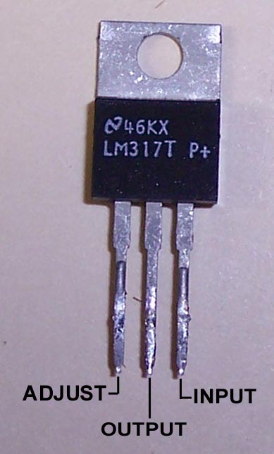
The IC is an LM317 adjustable three terminal regulator. Its pins are as shown in the picture below.
For a verbal description click here.
In this application the IC does not require a heat sink. It only runs warm to the touch.
These ICs have one very bad tendency. That is to oscillate at about 1 megacycle. They can usually be tamed by connecting a 0.1 microfarad capacitor from the input to ground. You may think this is redundant because there is already a 300 microfarad capacitor from that point to ground. A capacitor that large is made by rolling a long strip of aluminum foil into a cylinder. This structure has a considerable amount of inductance at 1 megacycle and higher. The 0.1 microfarad keeps the input at ground potential at high frequencies.
Removing Parts From a PC Board.
These modifications require that many components be removed from the PC boards. This must be done properly to avoid damage to the boards. I advise against heating the solder while pulling on the component on the other side. This is all but guaranteed to damage the component, but in addition, the foil on the board may be damaged and the solder will not be removed.I acknowledge there are other ways of unsoldering parts from a PC board. If you have and know how to use a solder sucker, or vacuum pump, then continue to use it. If you have little or no experience in desoldering by all means read on.
The solution I prefer is a product known as Solder Wick or Chem-Wik, depending on who makes it. It is copper braid that has been soaked in a rosin based soldering flux.
You may have read somewhere that it is possible to use the copper braid from old coaxial cable. This can work if you coat the braid with non-acidic soldering flux. If you want to use this method be sure not to buy acid based flux. If you do, don't complain to me when your generator rusts out. By the time you buy the flux you probably won't save any money so you might as well break down and buy the solder wick.
To use solder wick you must have everything hot. Solder can only flow if it is a liquid. It will only be absorbed by the wick if the wick is as hot as the molten solder. Here's how to do it.
- place your soldering iron tip in contact with the solder joint to melt the solder and get a little fresh solder on the tip.
- Lift the iron tip and place the wick between the tip and joint. The solder will likely cool and congeal but don't panic. Keep applying heat and it will melt again.
- As soon as the solder becomes a liquid again it will begin to be absorbed into the wick.
- Move the wick around to wipe up the solder. It's no different from wiping up water with a paper towel except the whole thing is at a temperature of 700 degrees F.
- When the wick becomes saturated move up to an area that has not absorbed any solder. Solder will travel up the wick as far as it is hot.
In most cases, if you did a good job, the part will just fall out of the circuit board.
Modifying the Power Supply.
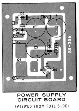
Refer to the PC board layout and photograph below. Keep in mind that the drawing is shown from the bottom of the board while the photo is from the top.

Here are the steps to complete the modification.
Connect a voltmeter from ground to the output lead of the IC regulator. Note: the chassis is not ground on this instrument. Find ground at the negative end of C4 or the black binding post on the front panel.
- Remove the following parts from the power supply circuit board.
- C3
- Q10
- D7
- R28
- Locate a 0.1 microfarad 100 volt capacitor. A ceramic disk was used here. Insert the leads through the holes that were originally used for R28 and D7. Use the holes that are closest to C2. Solder the leads on the foil side of the board and cut off excess lead length.
- Insert one lead of a 120 ohm resistor into the remaining hole originally used for D7. There is an unused pad with a hole to the left of Q10 in the drawing, right in the photo. Insert the other lead through this hole. On the foil side bend this lead flat against the board and route it so it touches the point where the positive lead of C4 is soldered to the board.
- Solder the resistor lead to the positive lead of C4, use fresh solder, do not just heat the old solder and stick the lead into it.
- Solder the resistor lead to the previously unused foil. Solder the other lead at the former site of D7 and cut off the excess lead.
- The photo shows a 3.9 k ohm resistor. This resistor was selected using a DMM for a value of 4.3 k ohms. If you have a 4.3 k ohm 5% ˝ watt resistor feel free to use it. If you don't, go through your stock of 3.9 k ohm 10% ˝ watt resistors until you find one with a resistance of 4.3 k ohms.
- Locate a 10 microfarad 50 volt capacitor and solder the resistor leads to it as shown in the photograph.
- Form the capacitor leads to fit the holes and insert the negative lead into the hole that used to be the negative lead of C3. Insert the positive lead into the remaining hole that used to be for R28.
- Solder the leads to the foil and cut off excess lead length.
- Refer to the photo of the IC regulator and form the leads to fit into the former home of Q10 as follows.
- Adjust to the B (base) terminal.
- Output to the E (emitter) terminal.
- Input to the C (collector) terminal.
- This is not a really comfortable fit for the IC. Bend and form the leads carefully before attempting to insert them into the holes.
- Solder the regulator leads on the foil side but do not cut off the excess leads. The leads will come in handy to clip meter leads to for testing the power supply.
Plug in the power cord and turn the power switch on. The meter should read somewhere between 44 and 45 volts. It's good for the voltage to be a little high but if it is around 50 volts, you have a broblem.
Measure the distortion. Low enough for you yet? If not, continue.
- Introduction and Modifications 1, 2, and 3.
- Modification 4, Power Supply Regulator. (You are here.)
- Modification 5, Decreasing Distortion in Amplifier.
- Modification 6, Mounting Power Transformer Outside the Case.
The day that the Heath company closed its doors
was a sad day indeed for electronics home brewers.
Before it existed there was nothing in the world like it,
It was never equaled by its wood-be competition,
And there will never again be anything like it.
HomeOr use your "Back" button to return to where you were.
This page last updated April 15, 2006.