Circuit Diagram
Parts List
Circuit Explanation
Helpful Links
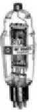
This is the circuit diagram for the 811-A Tesla
coil. As you can easily see, it is a Hartley oscillator
with the inductor tapped approximately in the
center. L2 sits atop the coil enclosure, where it can
be moved around to change its magnetic coupling
with the primary, enclosed within the box. The
coil will make a shrieking 6" thin blue arc and
relies on the "sputter" mode of operation.
C1...............................................0.001
microfarad, 10 kVDC mini-doorknob (Hosfelt, $0.99)
C2...............................................0.02 microfarad, >
3 kVDC, use series / parallel ceramics (Hosfelt)
C3...............................................microwave oven capacitor
(AMI Parts, Inc.)
L1...............................................32.0 turns #14 magnet
wire on 3.25" OD form (OR 30.0 turns on 3.5" Sch. 40 PVC pipe,
in this case tapped at 6.5 and 13.5 turns)
L2...............................................7.5" long winding
of #28 magnet wire on 3.5" Sch. 40 PVC pipe
L3...............................................150 microhenry filament
choke [this is really not necessary] (Hosfelt)
R.................................................2 8.2 kohm, 10-watt
wirewound resistors in series (Hosfelt)
Diode..........................................Microwave oven diode
(AMI Parts, Inc.)
Transformer.................................Microwave oven transformer,
with added filament winding (see text)
How this coil works: The circuit is very straightforward and this coil makes a good first project. For one thing, I bought all the parts for less than $20, including an 811-A and socket from RF Parts Inc. Now their prices are a bit higher, but you get a higher-quality tube made by a reputable factory. L1 and C1 are the tank circuit of the Hartley oscillator. C1 is too much capacitance when connected across the entire coil, so I connected it at the tapped position shown to increase the resonant frequency. For a description of general Class-C oscillator behavior, see the 833 coil page. In the case of the 811 coil, gridleak RC causes a "sputter mode" action at about 15 kHz.
Unlike the 833 coil, this one doesn't use "level shifting" in the power supply, but rather simple half-wave rectification. The reason is that the 811-A would be operated far above its voltage rating if level shifting were employed. One nice feature I designed into this coil is the DC-grounded plate. This is for safety to users, since my intention with this coil was to build and sell it. The entire tank circuit, the plate cap on the tube, and the other exposed parts of the circuit are at a safe ground potential (though you can still get a little RF burn if you touch these areas.) The diode rectifies for high voltage negative, which goes directly to cathode.
You will need to figure out a filament power situation for this coil. Either use a conventional filament transformer and run the plate DC hot in the standard way, or wind some well-insulated wire onto the microwave oven transformer as shown so you get 6.3 VAC across the filament.
In my prototypes, the primary tank coil and all the other circuit components were encased in a wood box with black plexiglas lid. The primary coil stood upright and its position was marked by a circle inscribed on the lid. The secondary was positioned to be freely moved on the lid, so the user could change magnetic coupling. Also, two binding posts were provided, one which allows the secondary base lead to be grounded, and the other which allows the secondary to be base coupled to the RF hot plate end of L1 for more spark.
There is no primary tuning. Tuning is accomplished by adding capacitance to the free end of L2, such as a metal drawer-pull, quarters, nuts and bolts, whatever works. You should require very little capacitance to bring the secondary into resonance. L2 produces about 6" of screaming blue tendril when the circuit is operating right. It's real obnoxious to listen to for more than a few seconds (the sound is the result of "sputter" mode at 15 kHz). This coil drives a flask of neon quite nicely as a plasma display when at lower coupling (you don't want to puncture the glass).
Note: many people in the Tesla coil / amateur
radio community like to overdrive the 811-A. Note that the tube is
at its maximum ICAS ratings before any color shows on the plate
(download the spec sheet below), but this circuit keeps the plate dark.
Bypassing the sputter mode will cause the plate to run red hot.

Click to download the RCA 811-A
specs (zipped jpegs)