 |
www.angelfire.com/dragon/letstry
cwave04 at yahoo dot com |

|
|
|
A bit of abstraction
The great usefulness of finite automata stems from its abstractness. If we
learn to deal with this abstract concept then we can easily cast our
findings in any other
concrete set up and reap the benefit thereof. We have seen
in the last page that a finite automaton is simply a collection of 6
things (a 6-tuple) :
(A,B,S,f,g,START),
where
| Abstract symbols | In our Humpty Dumpty example |
| A is the (finite) input set |
A={Smile, Punch} |
| B is the (finite) output
set |
B={Normal, Smile, Raise eyebrow, Scowl, Growl, Grimace} |
| S is the (finite) state set |
S={Ordinary, Happy, Angry, Furious, Surprised} |
| f is the output controlling
function |
See below |
| g is the state controlling
function |
See below |
| START is a special member of S and is
called the initial state, the state from which
the automaton starts. |
START=Ordinary |
There are two popular ways to write down the
functions f and g, which we discuss below.
Method of tables
In this method f is written as a table. There
is one row for each state, and one column for each input. The table for
our Humpty Dumpty example from
the last page is shown below. To compare this with the example click
here.
|
Inputs |
| States |
|
|
Smile
|
Punch |
| Ordinary
|
Smile back
|
Raise eyebrow
|
| Happy
|
Smile back
|
Raise eyebrow
|
| Surprised
|
Normal
|
Scowl
|
| Angry
|
Scowl
|
Growl
|
| Furious
|
Scowl
|
Grimace
|
|
This table tells you to produce output f(a,s)
if your current input is a and the current state is
s. Simply look up the the entry in the row for
headed by s and column headed by a.
To fix the ideas let's do the following exercise. First click the example
link above (if you have not done so already) to open a
new small window containing only the Humpty Dumpty example. Turn the mind toggler
on, so that you can clearly see the states at each
step. Press reset to start the exercise. What is the state now ? It is
"Ordinary", which is the START state.
Suppose that the input is going to be "Smile". What
will be the output then? In other words what is
f(Ordinary , Smile)? The table tells
you that it is "Smile
back". Thus, pressing the
"Smile" button will cause Humpty Dumpty to "Smile back". Check
that this is
actually so by direct experimentation. Similarly try out
some other examples and compare with the table.
Next we shall discuss g, the
state controlling function. It can be
written as another matrix such that the entry in the row corresponding to
s and column
corresponding to a is
g(a,s):
|
Inputs |
| States |
|
|
Smile
|
Punch |
| Ordinary
|
Happy
|
Surprised
|
| Happy
|
Happy
|
Surprised
|
| Surprised
|
Ordinary
|
Angry
|
| Angry
|
Angry
|
Furious
|
| Furious
|
Angry
|
Furious
|
|
A cursory glance at the two tables may lead you to the wrong belief that
they are essentially the same with "smile back" in the first table is
always replaced by "happy" in the second one, and similarly "ordinary" by
"normal", "raise eyebrow" by "surprised" etc. But this not always true,
simply because there are unequal numbers of outputs and states. In
particular, look at the bottom righthand corner of the tables. It seems
that "grimace" in the first table corresponds to "furious" in the
second table. But the entry just above it belies this speculation. There
we have "growl" in the first table though the second table entry is still
"furious". We leave it to the reader to check correctness of the table by
direct experimentation.
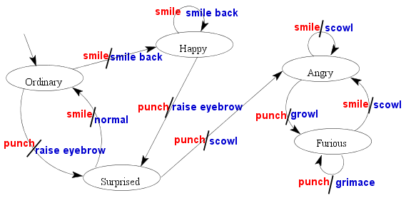
Method of diagrams
This is another method of representing the same information as conveyed by
the two tables above. It is best explained via an example. Below we construct
the diagram (called transition diagram) for our by-now familiar
Humpty Dumpty example.
The diagram, as the reader can easily see, consists of some nodes
shown here as ellipses labelled by the names of the states. A number of
arrows connect the nodes. Each arrow
is labelled by a pair of items separated by a comma. A close inspection
will reveal to the reader that the first item of the pair is always the
name of some input, while the second one refers to some output. Consider
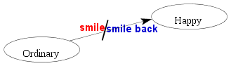
for example the typical portion of the diagram shown below.
The diagram shows only two nodes, corresponding to the states "ordinary"
and "happy". The arrow leads from "ordinary" to "happy". The
label pair associated with this arrow is ("smile","smile back"). This means
that if Humpty is currently in the the "ordinary" state and the input
is "smile" then he produces the output "smile back" and (following
the arrow) internally moves to the state "happy".
This explanation does not, however, tell us anything about the tiny arrow
that leads from nowhere to the "ordinary" node in the complete
diagram. Well, it is not a typo. It simply says that
"ordinary" is our start state.
The reader may naturally ask "Which method is better --- the table one or
the diagram one?" There is no unique answer. The diagram method is more
appealing to the eye, and often easier to construct by hand. The table
method, on the other hand, is better suited to computer
implementation, a topic which are presently going to look into.
Implementing a finite automaton
For this section we assume that the reader is reasonably familiar with
some high-level computer language like C or ForTran. We shall present all
our code snippets in C. All our indices will start from 0 onwards.
Our C coding of a finite automaton will come as three modules.
- The matrix module
- The output module
- The driver module
The matrix module
The matrix module will consist of two matrices like those we have presented
in the method of tables above. To get these matrices we shall encode the
sets A,B,S as sets of integers as follows.
A = {0,1,...,nInput-1}
B = {0,1,...,nOutput-1}
S = {0,1,...,nState-1}
Here nInput,nOutput and nState refer ,respectively,
to the numbers of inputs, outputs and states.
The matrix outMat for the output controlling function, and
the matrix staMat for the state controlling function will
then be matrices like

int outMat[nState][nInput];
int staMat[nState][nInput];
|
Depending on the context, the exact entries in these matrices may be
hardcoded in the program (in the form of initialization) or read in from
some file during execution.
The output module
In our Humpty Dumpty example, the outputs were merely words
that denoted
some actions. In a reallife problem, however, mere words will not do, rather we
have to indeed perform some action. Actually, even in the toy
example, some action was performed, viz., the appropriate image was
highlighted. A little javascript program sitting behind the html file was
doing that service for us. Any such routine(s) helping us to perform the
output actions will go in the output module. A generic interface to this
module may be provided by an envelop routine output of the form
output(int whichOutput) {
  switch(whichOutput) {
     case 0:
      /*write appropriate code
        to handle output 1*/
      break;

      /* other cases go here */

     case nOutput-1:
      /* handle this output  */
      break;
     default :
      fprintf(stderr,
              "Unknown output number [%d]\n",
              whichOutput);
    }
}
|
The driver module
This is in some sense the main module, though it is the simplest module to
write. It is a code with an infinite loop (assuming appropriate exit
statements to be embedded in the output module). It is so very simple that
it is better to give the code directly rather than try to complicate it
with explanations.
driver(int startState) {
  int state, inp;

  state = startState;
  while(1) {
     inp = input();
     output(outMat[state][inp]);
     state = staMat[state][inp];
   }
}
|
As any experienced programmer will readily see, the above code is not
meant to be used verbatim for each and every problem that might call for
using a finite automaton. This is the working main core. The reader is
most welcome to modify the code to suit the problem at hand. In
particular, one modification that may be useful in many situations is to
remove the infinite loop, and make the routine carry out one single step
only. Then the user has to call the routine again and again to move
through the execution of the automaton. In this case it is important to
declare state as static inside the routine.
Now that the reader is resonably familiar with the implementation of
finite automata, it is time to take a look at some practical uses of
this concept.
|