
1. Remove engine wiring harness from D16Z6. 2. Open wiring harness loom from the fuel injectors side to the engine / ECU connectors. This is on the main loom that goes across the engine you can leave the small loom that goes to the sensors alone. 3. Label wires at junction C125 (Which is at the right rear of the engine bay on a 92-95 SI/EX) and also on the side by the main harness. All the wires are yellow with a black stripe so pay attention. C125 looks like a plug that is blocked off you can’t miss it 4. Cut wires close to the C125 connector and close on the main harness then reconnect them so that the connector wiring is now very short 5. The 8th wire on the C125 junction needs to be cut off the 14 pin connector and extended to the engine / ECU connectors You can use the cut wires from the above steps to extend it so you can keep the wire all one color. Remember solder and heat shrink! 6. Cut off the 14 pin connector that is also at the right rear of the engine bay label them if you think you will get confused, but every wire on that connector is a different color than each other so there should be no confusion. 7. Pull all wires from the 14 pin connector to the other end of the harness 8. Cut off the two pin connector with the thick gauged black with a white stripe and the black with a yellow stripe wires at the right rear of the engine bay 9. Pull these wires to the other end of the harness 10. Cut the thick gauged black with a white stripe and the black with a yellow stripe wires to the length of the engine / ECU connectors and put connectors of your choice on them. This is the only place I used quick disconnect connectors in my install since the wires need to be able to be unplugged in case I pull the motor out for maintenance. See the connection below after step 16. 11. After all the wires have been pulled from the right to the left close the harness back up like how it was and recover it with new electrical tape. 12. Tie wrap the C125 junction to the main harness so it won’t move and so when the harness is installed it will be hidden under the intake manifold 13. Cut all wires from the 14 pin connector to the same length to make the connections cleaner 14. Build the #2 connector side B,15 pin connector as per the pin out below
Engine connector #2 Pin out side B (Male side)
These are the 14 wires from the connector you cut off on the right side of the engine bay.
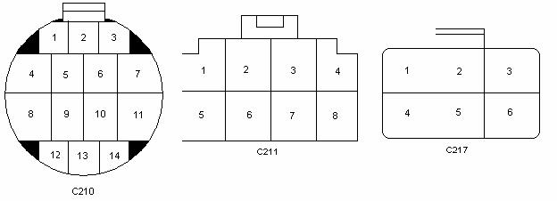
15. Cut off the wires from connectors C210, C211, C212 (In the under hood fuse box, closest and parallel to the firewall), and C217 as you need them to build the #2 side A, 15 pin connector. See here for the location of the connectors
16. Connect the thick-gauged black with a white stripe and the black with a yellow stripe wires from the car’s harness you just cut to the ones you just pulled on the engine wiring harness. If you do not do this the car will not start and the distributor won’t have power! When you are finished with that continue with building the Molex side A connector as per the pin out below.
Click here to see the completed wiring connectors.
Engine connector #2 Pin out side A (Female side)
These are the wires that are cut off the stock wiring of the car to be connected to the wiring you moved on the D16Z6 wiring harness. The two cars have them on opposite sides of the car hence the reason for moving the other wiring to this side. There are only a couple exceptions that didn’t make it worth it to have an extra wiring harness on the right side of the engine bay. Not to mention all the wiring is on one side and away from the drive belts this way. It also makes for less clutter in the engine bay.

17. Put the harness back on the motor and make sure it’s secure and installed properly so nothing gets damaged or tangled in a rotating part
18. Pull out the left over plugs and wiring that are no longer connected to anything to make the install cleaner.
The Engine bay wiring should now be done and there should be no more wiring going to the right side of the engine bay at all. The white plug C313 that is in shape left behind on the right rear of the engine bay could be cut off and the wires tucked as they will no longer be needed at this point. Also you could then close up the harness on that side.
Here is a picture of the harness I'm talking about.
