
This is my subwoofer idea. I want to use a total of thirty-six (as in 36) 8" drivers, eighteen per side, in a type of Linkwitz open-baffle subwoofer, but with a modification.
First of all, why 8" drivers and not something larger? Well, I have a bit of a size constraint in terms of both height and depth. I did not want the total height or depth to exceed 70cm/27.5" (foot included). In that size constriction, I can use eight 12" drivers per side (in 2 X 2 formations, see further down for details), or as I have chosen, eighteen 8" drivers (in 3 X 3 formations).
The 12" drivers will probably have more power-handling, but since I am only going to use a single 56W Gainclone amp per driver, the 100W that the 8" drivers are rated at is sufficient.
Now lets look at aggregate size. An average 12" driver has an Sd of about 490 sq cm (square cm). An 8" has an Sd of about 230 sq cm. So, for eight 12" drivers per side, the total radiating surface will be 3920 sq cm (8 X 490 sq cm). For eighteen 8" drivers the total radiating area will be 4140 sq cm, so the difference is not that great, but still worthwhile. Furthermore, consider this- the Sd for a 21" driver is about 1630cm sq cm, and for a 24" driver it is about 2240 sq cm. So, the combination of eighteen 8" drivers will have almost the same radiating area as two 24" drivers! (evil grin) ;-)
The next reason has to do more with the application I want to use them in. The cross-over point will be approximately at 50Hz, and I would like to drive the subwoofer below it's Fs, i.e. in a open-baffle (Linkwitz style), ELF design (this will become clearer as I add the illustrations). The 8" drivers have a higher Fs than the 12" drivers, so this is also beneficial, and fits in much better to my overall design idea.
The last consideration, and the one that really swinged it for me, is price. Locally I can get the thirty-six 8" drivers for much LESS that I can get sixteen 12" drivers. Admittedly the 12" drivers have a higher power-handling capability than the 8" drivers, but like I explained above, this did not figure so strongly in my calculations.
Ok, on to the idea. The shape if viewed from the top (with top and bottom baffles removed) will look like this:

The drivers will be mounted on the inner panels, in a 3 X 3 formation:

The cones will face each other in a push-push formation. The view from the top (with top and bottom baffles removed), after the drivers have been mounted will look something like this:

I will add horizontal divisions between each three drivers (which will also double as brace between the baffles), and the result from the from will look something like this (note- I colored the inner\rear baffle a light grey, so that the drivers can stand out, only for the purposes of this illustration):

Now for the modification that I talked about earlier. I want to add something to restrict airflow to the rear (similar to aperiodic loading, but less restrictive). This will be mainly to raise the Fs of the driver-array to above 50Hz (the cross-over frequency). This has been added in the following illustration:

I have come up with one possible modification, and that is to stagger the 'steps' on which the drivers are mounted. This is to reduce the chuffing effect, as well as to reduce any type of transmission-line resonances (the drivers could see the slot opening as just a short TL). That idea is illustrated below:

Well, that's my idea. Comments will be welcome :-)
Deon
First of all I need to thank especially Bill F. from the Full-Range Driver Forum. I posted my idea there, and he gave me a lot of guidance, and it is thanks to him that I can now more clearly evaluate this project and it's viability.
Bill indicated that I might not be able to get a lot of SPLs at low frequencies due to the steep roll-off (between 12dB/octave and 18dB/octave) a design like this will be subject to. Even my boast of a very high Sd will not be enough.
For a totally open-baffle ELF design, the roll-off rate will be 18dB/octave (room gain not taken into account). For an aperiodic design such as the one I'm proposing, it will be much closer to 12dB/octave.
Given this, it means that I will have to boost the signal 12dB for every octave that I want to go down. In the design suggested above, that means I will have to boost the signal a total of 36dB for the lowest octave!
So, knowing this and armed with some figures that Bill supplied, I decided to crunch the numbers a bit, and came up with the tables that are to follow.
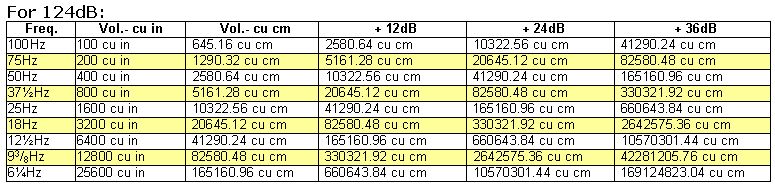
Please note the following regarding the tables. The steps in frequency are only half octaves down (or up, depending on which way you read the table), so to make it easier to properly understand the teable I highlighted every second line in yellow. The lines in white are all a full octave apart, as are the lines in yellow.
Here is the key to the tables:
The first column shows the frequency, the second column show the volume of air in cubic inches (cu in), the third column the same volume in cubic centimeters (cu cm). The next three columns show the amount I'd need to be able to generate if I wanted to boost that frequency with either 12dB, 24dB or 36dB.
The first table shows the volume of air that must be moved at each frequency for a SPL level of 112dB.

The second table shows the volume of air that must be moved at each frequency for a SPL level of 115dB.

The third table shows the volume of air that must be moved at each frequency for a SPL level of 118dB.

The fourth table shows the volume of air that must be moved at each frequency for a SPL level of 121dB.

The fifth table shows the volume of air that must be moved at each frequency for a SPL level of 124dB.
Now let me put these tables into perspective. My Sd as stated above is 4140 sq cm. Let's assume that the 8" drivers have an Xmax of 3mm (i.e. 3mm maximum one way), and 3mm = 0.3cm. So, the total volume of air I'll be able to move is 1242 cu cm.
Next, let's take a reference level of 112dB. If I want to go from 50Hz down to 25Hz, I need to be able to move 2,580.64cu cm. That is already nearly double of what I have. To be able to go down to 6Hz I will need to be able to move a MASSIVE 660,643.80 cu cm! On the other hand, do I really WANT to play 6Hz at 112dB? I think not!
Now, let's change the rules a bit. Say below 25Hz I decide to reduce the boost level from 12dB/octave to only 6dB/octave. This is not illustrated in the tables, but can be derived from them- boosting at only 6dB\octave is the same as boosting over only half an octave at 12dB\octave. So, if we look at it now, the figures read as such:
For 50Hz at 112dB, we need to move 161.29cu cm
To boost this with 12dB down to 25Hz, we will need a volume capability of 2580.64 cu cm.
To boost at 6dB\octave down to 12.5Hz, we will need a volume capability of 20,642.12 cu cm, and for 6Hz we need 165,160.96 cu cm. That's still a lot, but certainly a lot less than 660,643.80 cu cm.
Now I am still not home free, but I have a much better idea of the challenges that lie ahead :-)
Deon
