Site hosted by Angelfire.com: Build your free website today!
1/35 UH60A Blackhawk Iraqi POW carrier "Tinnin"

1/35 scale UH60A
Desert Storm

MRC 1/35 Blackhawk, Desert Storm Veteran
"Tinnin"


This is a BIG article, let it load!


I have wanted to build a 1/35 scale Hawk since I worked on them in the early 80s as a young PFC. A couple of years ago, MRC Acadamy sent us thier first in the line, kit 200413, which can be built as an A or an L. The conversion to an L consists of adding a decal to the fuse to represent the locker on the right side. Not convincing in the least, and I prefer the later A model with the Hover Infra Red Supression System (HIRSS).

First Impressions: 
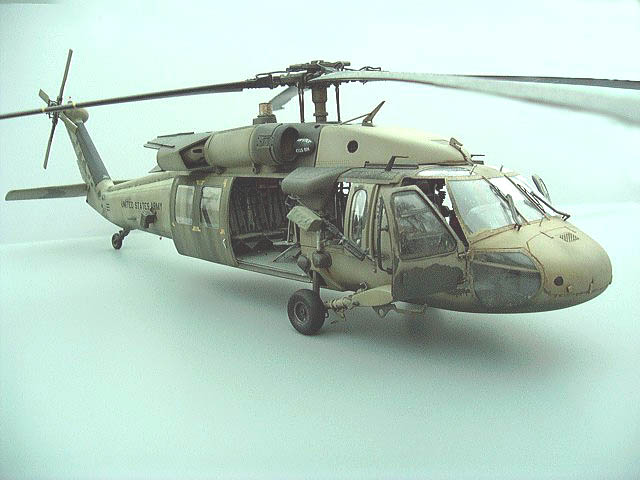
Big kit, big box, big price tag. I got a second one at Hobby Lobby for half off, which brought my total to $26USD! 
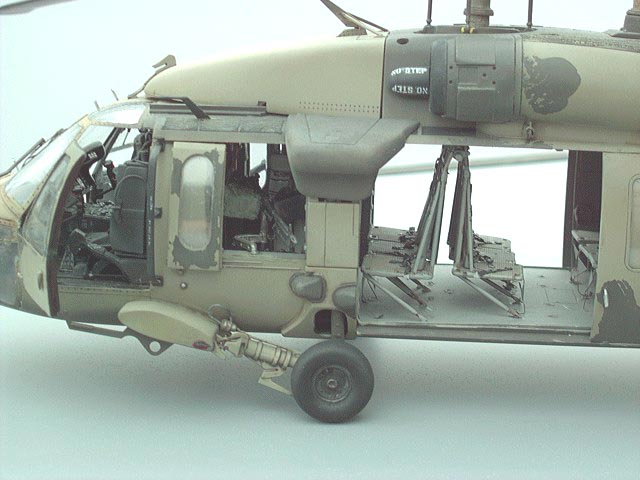
A couple of hundred parts with fair to soft molding, but thats not really a problem. Full interior detail with the best crew seats I have seen. Super crisp clear parts and options for the outer wing tanks. A/L version has standard M60D guns with fairly good detail.This will be a BIG model, with a overall lenght of just over two feet. Even if you plan to build this thing Out of the Box, you will spend at least 20 hours building it, so plan accordingly. I cut each peice away and cleaned it up prior to starting the kit, which seems to save time for me. I painted my kit with overall Helo Drab by model master, and then applied a custom sand mix over scrubbed-on rubber ceement in accordance with published photos of Tinnin.
A series of buildup articles have been featured at Aircraft Resource Center and you can reference these articles as well for construction tips.

I applied just about half a sheet of Eduards incredible photo etch to this kit, and used all of Cobra Companies UH60 Update set. both are well worth the money, but parts will overlap. YOu can get away without the PE, but it provides you with all of the under-seat bracing for the troop seats. I did not start with the interior as instructed, instead I moved to the fuse to bolster it up: I like the interlocking tabs to keep things aligned but I aslo added more tabs to help with alignment. Thin strip was added to the tail rotor driveshaft covers for the Dzus fastener clips, all the way up around the gearbox. I also cut out the molded vent and installed brass screen. I scribed the lines around the cowlings deeper to show natural shadows where the real components come apart, and drilled out the Dzus fasteners for added depth. Moving to the upper engine deck (part 83) i added and reinforced parts B18 before determining the exact location of the HIRRS exhast stubs (parts B14-17) The HIRRS are molded in one solid piece, but they have two cold air inlets at their forward face. I drew these in, drilledholes and cut them to shape, making two eliptical holes per side. There are great photos of this in UH60 Walkaround on page 19. Also you can cut out the dimple for the inlet particle separator and install a hunk of brass tube. Test fit everything and paint the HIRSS exhausts Testor Jet Exhaust, the perfect shade for these units. I made hinges for the engine nacelles which double as work platforms from .040 strip stock and brass stock, bent and filed to shape.
The wheels were detailed with a slug of stretched sprue isntalled in a drilled hole in the wheel hub for the valvestem, and a small ring of aluminum tube was added for depth on the axle. The tailwheel and strut was detailed the same way, and the molded wiring was sanded off, installing wire to a square of strip stock for the tailwheel unlock. Another photo of this is on page 25 of UH60 Walkaround. Knowing that the tailwheel now outshone the forward gears, I had to upgrade them, and upgrading they recieved!

The lower struts were detailed with 3 strips of stock running the circumference of the lower unit, and a wire was added running up the top inboard side for the brake line. Two hunks of telescopic tubing added to the end represent the brake quick disconnect, and a hole was drilled to recieve the brake line (walkaround page 16). I set the fuse parts on a block to keep it at the proper level and assembled the lower strut parts to the stubs (parts B31/34) and attached this to the fuse with poster putty to get my proper alignment. If you dont align this all properly now, and get the angle of the dangle set, your model will lean over later on. When the cement on the lower strut to stub has dried, take it all off and put it aside for later. Go ahead and enhance any further details you wish at this point on the outside, such as adding APR 39 antennas from punched out stock, drilling for your landing light, etc. The panel lines tend to fade as they approach the split line, so rescribing will be needed, but thats a quick job. If your planning on cutting out your doors for the Cobra Company replacement doors, follow thier instructions to the letter, Chris at Cobra planned it just right!


Lets work on the interior, plan to spend several days here. You will find that there are serious gaps that need to be addressed with strip stock (stock up on stock!!)    The floor simply does not fit, and the problem is the cargo hook housing. Sand about half of that away and you will see a maor improvemtn in the fit. Either use the photoetched replacement panels from Eduard for the sidewalls or make your own as I did, adding stock to the sidewalls and the broomclosets(B28/29). I would wait and drill your holes for your armor later, ensuring that the alignment for the armor is correct.
Whether you detail the kit seats or use the Cobra Company seats, you can seriously improve them in under an hour. Drill small holes in the lower front ends of each rail to accept thin wire, for the seat lock. Leave plenty and make sur you use very thin flexible wire. Determine where your seat will set on the rails, and make a small lock out of strip stock, adding this to the left side of the seat. Run the wires to the backside of the lock handle. Now run another wire up and over the frame for the ICS cord. The seats will be "handed" according to this cord, so plan accordingly. Each has the wire runing over the frame to the outboard side, looped under the headrest and over the shoulder, with a thicker part at the end for the plug. If you use the cobra set, add the ammo can boxes at the back of the seat with ICS control, and wires running from that down to the outboard side of the fuselage. I made a bag from folded foil and hung that under the ammo canholders. I also made pen clips from foil and added that, with simulated pens from sprue. The seat armor takes a bit of thinking through as well, so temporarily install your seats to getyour clearances correct. Each peice of armor was detailed with strip stock adn wire for the release handle, and mounted up so it would fit correctly when the seat was intalled. Actually, this was left out until the model was complete and added later with the doors off. Triangular reinforcemnts help to keep it sturdy. The extended version will be more prone to failure so thick wire may be preferable to sprue. (you may wish to check the articles I have at aircraftresourcenter.com for the full articles on how to do all this)
Let all this dry up, and walk away for a few days, the real work is about to begin.

The time has come and at this point most modelers give up on this kit, close the doors and blast it with green.

Not so! Follow me, and you willhave not only a convincing model, but one that will amaze and astound your freinds!
*yes, believe it or not I DO have a life!*

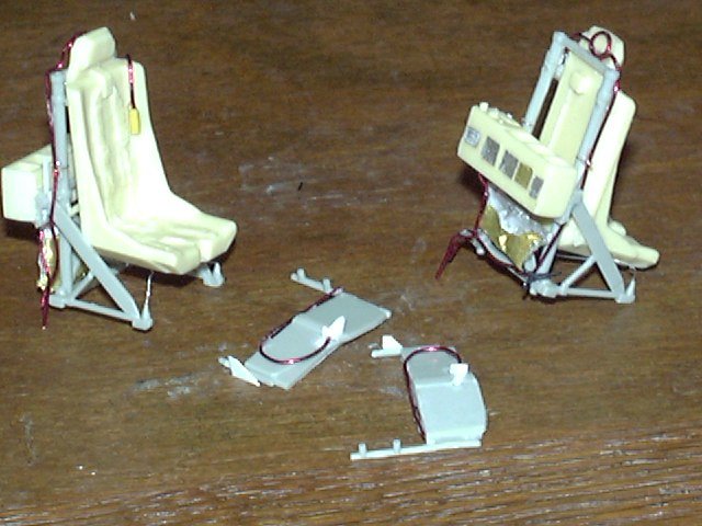
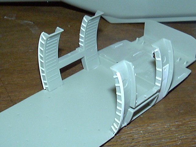
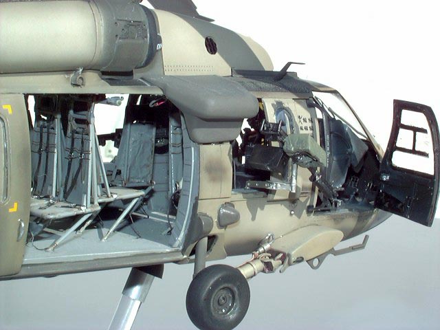
Y ou will be making a total of 12 troop/ crew seats, dont be led to believe that there are 11 troops seats, there are only ten.Remove each part from its sprue with new Xuron shears, clean that part and make damn sure you bag it with like numbered parts, these parts are not only different but look the same. I used baggies and marked boxes just to keep it all organized.

If you follow the kit seat installation insructions, you will go nuts. Try this instead:

Assemle your seats by row, the back row (mark on the bottom, see pics) being row # 3and the CE seats being marked L and R as well. 
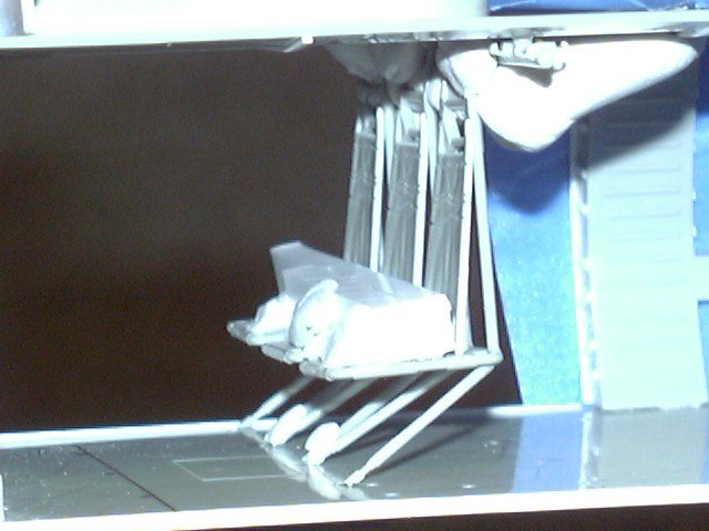
Each set has different hooks at the top and thier legs are oriented differntly. Start anywhere and build up the seats but leave off the legs. Temporarily assemble the roof to the back wall and broomclosets, and add your row of seats, allowing them to hang from the roof. Use a big tubular hunk of plastic and wedge the seats in place, and use more 
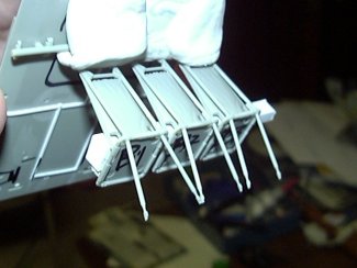
poster putty to get them just right. When its all adjusted, go ahead and put a drop of cement on the part of the leg that will attach to the seatbottom, after it sets for a minute, pull the roof off the broomclosets and add the legs. Let the glue set up a bit, and allow the legs to hang as they will. the idea here is that when the seats/roof are reinstalled, the legs will be compresed to the proper shape. Dont forget that the seat legs dont just hang down, they point aft to a central point between each seatback, except for the outermost leg, which hangs straight back. All legs point aft in all cases. Study the pics here and you will get a better idea of how to do this. In fact, this process will take three nights, and you will find it much much easier than going at it one seat at a time. When your all done with a row, pull that set out and set them in a box away from everytihng, ready to add any PE and paint. Make sure they are marked with position and row before you pull them out! I pulled an image of a US flag off the web, shrunk it down and mounted it inside the back wall behind the back row of seats. Thsi was a common practice during Desert Storm and an easy detail to add.
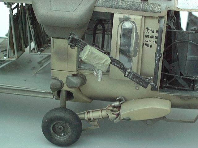
I added simple solder wire wiring for the CE commo cords and coiled that up, they should be long enough to loop back up on themselves, and small handles at the upper corners of the CE windows. The CE seats got simple commo footswitches added, as well as thier respective seatbacks. Each and every seatback has a nylon storage pocket. The front of the seatback is velcroed on, and it pulls off for whatever junk the CE has in there. Sometimes I use foil or paper to make the upper shoulder belts stowed inside of the seat, a very convincing trick, and I usually let a corner or two fall, since the real velcro wears out. 
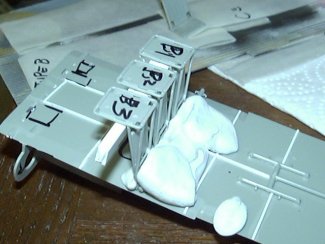
add stowage to the CE seats with putty between the back frames. (P 12-14 Walkaround) Does it show? you bet it does! Doing this is worth the effort you are putting into it. I painted the X shaped crossbraces seperately on the frame and added them to each seat before I installed it on the upper rail during final assembly.


The hard part is done, take a break, and come back later, youve earned it.
Ok, back to assembly, Your interior is ready for upgrade with either the cobra Company or Eduard parts, so just follow thier directions. I added communications plugs under the CE windows with Grandt Line bolts, drilled out the nose just under the windshield for the probe that sticks out there, and drilled small holes in the upper windows for thermometers made from straight pins cut to size. The M60Ds were cleaned up, and I used the Eduard PE parts to detail them. I covered the brasscatcher bag with foil for effect , and cut apart the mounting arms for proper articulation. One is mounted outside the window, one is stowed half folded inside the other window.

With most of the interior done, we can add further outside details. I made new tiedownrings from thick stock and wire, drilled out holes for the wiring from the Chaff and Flare dispensers and wiring from the ALQ 144 "disco light". Part D31 will not fit correctly so you will need to twist it to fit inside the molded receptacle and you can add Grandt line boltheads for detail. Its been said that you can leave the rotors unglued and push pull them out---I broke three of the mounting tangs, so they are not epoxied in place with tubular brass stock. The rotors got a set of wires from the central Bifolors mount out to the individual blade, entering it at the front where a molded nub is. That is an electrical cable for the de-ice strip. Each blade had its aft nubs carved off, and replaced with sprue for the shcrader valve and clear epoxy over sprue stock for the Blade Health Monitor. Overall black MR blades with helo drab green dynamic components components. You will find that if you build it up as in step 1, you will havce no place to put it! do this last... Tail Rotor blades are simliar, dark metallic grey hub, olive green paddles, with a dark metallic anti-erosion strip. I love the decals, they add a lot of character to the blades!

FINAL ASSEMBLY Wow, if you have read this far, you are as dedicated to this project as I was when I built it.
Now, lets get it all together and paint it. I chose the Tinnin option with its scoreboard of POWs carried, since I really love these worn out flakey faded schemes. Do your final assembly, and close of your interior with card or the doors, as you prefer. I used the excellent UH60 Black Magic Masks from Meteor Productions, and they are awesome!. Here is my color scheme: overall helicopter drab, then shaded with black over heavy panel lines and dark spots on the real thing. I mixed up Marine Corps Gulf Sand, Sand, Armor Sand and a touch of light grey for the final overal color,knowing I needed to apply it thin in spots and not at all on uppermost and lower surfaces. the mounting point covers for the external wings, rotor hubs, wheels and ALQ 144 are green and did not recieve sand paint.

I applied common rubber cement to areas where flaking showed on the real machine, and where flaking would be common, since this paint did not adhere well. After the rubber cement dried I sprayed on the sand mix just as a man standing on a short ladder in the field woudl do it, with random strokes, getting as high as he can on the short ladder. I sealed this with gloss and applied the decals, which settled OK with Micro Set. I applied a heavey oil wash, dirt and filth, then created anti skid walkways after taping them off to shape. Sprinkle baking soda over wet paint and when dry paint it filthy black, and drybrush. Another drybrushing with overall sand, more wear and tear, and seal with dead flat acrylic. Blackhawk DONE!

Walk away, make a baseplate and get ready for the admiration!
You have just completed in a few weeks what I labored over for about a year. Now, knowing what I need to do and what I have shared with you here, you can build yours much much quicker.
I hope youve enjoyed this article, and if there is any other information you need to know, feel free to ask.


Written Christmas Day, 2003. Who knows what next year will bring!?!

Back to Hoverlovers Model page

Photos © David Campbell