Figure
1 Donor chassis
before stripping

Click photo to enlarge
|
This is the chassis from the donor amp before
I stripped it (see figure 1). It was a very simple solid state amp, and
still worked, but sounded horrible!
There was nothing of use on the chassis, so it had to be stripped to
the bare metal.
|
Figure 2
Chassis Stripped and in process

Click photo to enlarge
|
Here, the chassis is undergoing modification
to hold the tube sockets (see figure 2). I chose to tap the chassis instead
of using nuts on the socket screws. At this stage the layout had already
been chosen by setting the transformers, tube sockets, and turret board on
the bare chassis to assure that there would be room to wire everything .
Also it is good practice to pre plan the wire routing before committing to
component locations. All of the holes for the controls required enlarging
to accept the new parts.
|
Figure
3 Gilmore Jr. parts (basic kit)

Click photo to enlarge
|
This is a picture of the parts I received
to build with (see figure 3).
Note: If you order a basic kit from Gerhart Amplification now, there
are more parts included than shown here. Also, there are more 1/2 watt resistors
pictured than are actually required to build the kit.
|
Figure
4
Chassis
Layout

Click photo to enlarge
|
Home-brew building, like prototype
building, is sometimes two steps forward and one step back. At the point
illustrated here, (see figure 4)
the tube sockets, transformers, and turret board are located. However,
after marking for the IEC jack (power cord), transformer wire grommets,
and speaker jack; the mounted parts were removed to do the final cutting
and drilling on the chassis.
|
Figure
5
Turret board layout

Click photo to enlarge
|
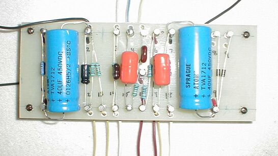
The turret board. Ready to be wired, and
have the components installed (see figure 5).
Note: This is a hand drilled prototype board, as you can see, the holes
are not perfectly aligned. The numbers were added with a Sharpie indelible
marker to facilitate the assembly instructions.
|
Figure
6
Checking the layout

Click photo to enlarge
|
To pre plan the wire routing, and make certain
the turret board was located properly, it was mounted to the chassis one
last time before committing to the final wiring and soldering process (see
figure 6).
|
Figure 7
Turret board assembled

Click photo to enlarge
|
With all the instructions and graphics supplied,
assembly of the components onto the turret board is not difficult
(see figure 7) .
It makes the job easier if the wires are soldered onto the bottom level
of the turrets before soldering components on the top level.
|
Figure 8
Ready
for final wiring

Click photo to enlarge
|
At this stage all parts are installed, and
it is time to do final wiring and soldering. Get everything ready before beginning
to solder. It makes the final wiring/soldering go much quicker. To go beyond
what is shown, (see figure 8) the wires can be cut and ends stripped to make
soldering a continuous process.
|
Figure 9
All wired up

Click photo to enlarge
|
Here, (see figure 9) everything is wired
and ready to test.
Note: The prototype turret board in this amp was originally designed for
a chassis with the tubes on top. Since this chassis has the tubes
hanging underneath, some of the wires from the tube sockets to the turret
board cross each other. This is not ideal wire routing, but it caused no
problems. ***Upon prior request, Gerhart Amplification will supply home-brew
builders with a mirror image turret board that solves this problem!***
|
Figure
10 Tubes, transformers and jacks
installed

Click photo to enlarge
|
The special design, heavy duty Mercury Magnetics
transformers can be seen well here (see figure 10). Since this chassis allowed
a good distance between transformers, and it made for convenient wire
routing, the transformers were not splayed (mounted perpendicular, or at
odd angles to one another). However, notice that they are intentionally
not in perfect alignment. In this case, that was adequate to prevent any
magnetic coupling noise between the power and output transformers.
|
Figure 11
Finished amp!

Click photo to enlarge
|
The chassis is back in the donor cabinet!
(see figure 11)
|
Figure 12
Finished amp (rear)

Click photo to enlarge
|
After trying several speakers, this 10" Eminence
/ MojoTone was chosen for its balanced and smooth tone. However, a vintage
12"
Jensen P12R sounded especially good! There just wasn't room to fit it into
the cabinet.
|