A Design
Exercise:
This is an example
application where in I applied the concept of PLD programming in an application.
The circuit to be designed was a Pulse Transformer Board which
will be used to trigger SCRs into conduction. The application was
supposed to control a 3-phase line voltage. Each phase to be controlled
needs two(2) SCRs. As a result, six(6) pulse transformer is needed.
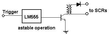
The OLD design approach was using six(6) LM555
timers as clock generator to drive the six(6) darlington pair transistor
which will eventually drive the six(6) pulse transformers. The microcontroller
needs six(6) available output lines for controlling the board.

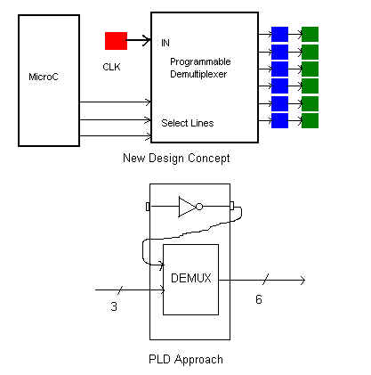
The PLD approach;
As seen from the diagram above, there are redundancy
with the clock generators, excessive I/O line usage.
The Clock Generator Circuit:
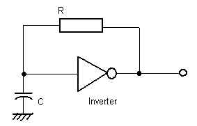
This is a classical clock generator circuit application
using an inverter, a capacitor, and a resistor.
The Overall Block Diagram:
The Abel
Source Code
Module SCRdriver
title ' SCR Driver Board for 3 Phase System
Written by: Rodelio P. Barcenas
September
1, 2000
'
" JEDEC filename output declaration
SCR device 'P16L8'; " SCR.JED is the target filename
" PIN Assignment Section
a,s2,s1,s0 pin 1,7,8,9;
Q1,Q2,Q3,Q4,Q5,Q6,b pin 12,13,14,15,16,17,18;
" SET DECLARATIONS
Transistor = [Q6,Q5,Q4,Q3,Q2,Q1];
Select = [s2,s1,s0];
" PROGRAM LIST
equations
b = !a;
" inverter equation for the classical clk circuit
truth_table ([ Select,b ] -> Transistor)" demultiplexer with select
[ 1 ,0 ] -> ^b000000;" lines and clk
as input
[ 1 ,1 ] -> ^b000001;
[ 2 ,0 ] -> ^b000000;
[ 2 ,1 ] -> ^b000010;
[ 3 ,0 ] -> ^b000000;
[ 3 ,1 ] -> ^b000100;
[ 4 ,0 ] -> ^b000000;
[ 4 ,1 ] -> ^b001000;
[ 5 ,0 ] -> ^b000000;
[ 5 ,1 ] -> ^b010000;
[ 6 ,0 ] -> ^b000000;
[ 6 ,1 ] -> ^b100000;
[ 0 ,0 ] -> ^b000000;
[ 0 ,1 ] -> ^b000000;
[ 7 ,0 ] -> ^b000000;
[ 7 ,1 ] -> ^b000000;
end SCRdriver
Abel Document
Generator
The Document written below is generated by
the ABEL software
Page 1
ABEL(tm) Version 2.00b - Document Generator 12-Sep-100 04:59 PM
SCR Driver Board for 3 Phase System
Written by: Rodelio P. Barcenas
September 1, 2000
Symbol list for Module SCRdriver
Q1 Pin 12 neg, com
Q2 Pin 13 neg, com
Q3 Pin 14 neg, com
Q4 Pin 15 neg, com
Q5 Pin 16 neg, com
Q6 Pin 17 neg, com
SCR device P16L8
SCRdriver Module Name
Select ([s2,s1,s0])
Transistor ([Q6,Q5,Q4,Q3,Q2,Q1])
a Pin 1 pos, com
b Pin 18 neg, com
s0 Pin 9 pos, com
s1 Pin 8 pos, com
s2 Pin 7 pos, com
Page 2
ABEL(tm) Version 2.00b - Document Generator 12-Sep-100 04:59 PM
SCR Driver Board for 3 Phase System
Written by: Rodelio P. Barcenas
September 1, 2000
Equations for Module SCRdriver
Device SCR
Reduced Equations:
b = !(a);
Q6 = !(!b # !s0 & !s1 # !s0 & !s2 # !s1 & !s2 # s0 & s2
# s0 & s1);
Q5 = !(!b # !s0 & !s1 # !s0 & !s2 # !s1 & !s2 # s0 & s1
# s1 & s2);
Q4 = !(!b # !s0 & !s2 # !s1 & !s2 # s0 & s2 # s0 & s1
# s1 & s2);
Q3 = !(!b # !s0 & !s1 # !s0 & !s2 # !s1 & !s2 # s0 & s2
# s1 & s2);
Q2 = !(!b # !s0 & !s1 # !s1 & !s2 # s0 & s2 # s0 & s1
# s1 & s2);
Q1 = !(!b # !s0 & !s1 # !s0 & !s2 # s0 & s2 # s0 & s1
# s1 & s2);
Page 3
ABEL(tm) Version 2.00b - Document Generator 12-Sep-100 04:59 PM
SCR Driver Board for 3 Phase System
Written by: Rodelio P. Barcenas
September 1, 2000
Chip diagram for Module SCRdriver
Device SCR
P16L8
----------\ /----------
|
\ /
|
|
----- |
a | 1
20 | Vcc
|
|
| 2
19 |
|
|
| 3
18 | b
|
|
| 4
17 | Q6
|
|
| 5
16 | Q5
|
|
| 6
15 | Q4
|
|
s2 | 7
14 | Q3
|
|
s1 | 8
13 | Q2
|
|
s0 | 9
12 | Q1
|
|
GND | 10
11 |
|
|
|
|
-----------------------------
Page 4
ABEL(tm) Version 2.00b - Document Generator 12-Sep-100 04:59 PM
SCR Driver Board for 3 Phase System
Written by: Rodelio P. Barcenas
September 1, 2000
for Module SCRdriver
Device SCR
Device Type: P16L8 Terms Used: 44 out of 64
Terms
Pin # | Name | Used | Max | Term Type | Pin Type
--------------------------------------------------
1 | a | -- | -- | --- | Input
2 | | -- | -- | --- |
Input
3 | | -- | -- | --- |
Input
4 | | -- | -- | --- |
Input
5 | | -- | -- | --- |
Input
6 | | -- | -- | --- |
Input
7 | s2 | -- | -- | --- | Input
8 | s1 | -- | -- | --- | Input
9 | s0 | -- | -- | --- | Input
10 | GND | -- | -- | --- | GND
11 | | -- | -- | --- | Input
12 | Q1 | 6 | 7 | Normal | Output
13 | Q2 | 6 | 7 | Normal | I/O
14 | Q3 | 6 | 7 | Normal | I/O
15 | Q4 | 6 | 7 | Normal | I/O
16 | Q5 | 6 | 7 | Normal | I/O
17 | Q6 | 6 | 7 | Normal | I/O
18 | b | 1 | 7 | Normal | I/O
19 | | 0 | 7 | Normal | Output
20 | Vcc | -- | -- | --- | VCC
end of module SCRdriver
The FUSEMAP
File
ABEL(tm) Version
2.00b JEDEC file for: P16L8
Large Memory Version
Created on: 12-Sep-100 04:59 PM
SCR Driver Board for 3 Phase System
Written by: Rodelio P. Barcenas
September 1, 2000
*
QP20* QF2048*
L0000
00000000000000000000000000000000
00000000000000000000000000000000
00000000000000000000000000000000
00000000000000000000000000000000
00000000000000000000000000000000
00000000000000000000000000000000
00000000000000000000000000000000
00000000000000000000000000000000
11111111111111111111111111111111
11011111111111111111111111111111
00000000000000000000000000000000
00000000000000000000000000000000
00000000000000000000000000000000
00000000000000000000000000000000
00000000000000000000000000000000
00000000000000000000000000000000
11111111111111111111111111111111
11111110111111111111111111111111
11111111111111111111111110111011
11111111111111111111101111111011
11111111111111111111101110111111
11111111111111111111011111110111
11111111111111111111111101110111
00000000000000000000000000000000
11111111111111111111111111111111
11111110111111111111111111111111
11111111111111111111111110111011
11111111111111111111101111111011
11111111111111111111101110111111
11111111111111111111111101110111
11111111111111111111011101111111
00000000000000000000000000000000
11111111111111111111111111111111
11111110111111111111111111111111
11111111111111111111101111111011
11111111111111111111101110111111
11111111111111111111011111110111
11111111111111111111111101110111
11111111111111111111011101111111
00000000000000000000000000000000
11111111111111111111111111111111
11111110111111111111111111111111
11111111111111111111111110111011
11111111111111111111101111111011
11111111111111111111101110111111
11111111111111111111011111110111
11111111111111111111011101111111
00000000000000000000000000000000
11111111111111111111111111111111
11111110111111111111111111111111
11111111111111111111111110111011
11111111111111111111101110111111
11111111111111111111011111110111
11111111111111111111111101110111
11111111111111111111011101111111
00000000000000000000000000000000
11111111111111111111111111111111
11111110111111111111111111111111
11111111111111111111111110111011
11111111111111111111101111111011
11111111111111111111011111110111
11111111111111111111111101110111
11111111111111111111011101111111
00000000000000000000000000000000*
|