
 The illustration fig. A opposite page shows how headless dress makers pins and a wire connection for ground 0 volts can join a 34 way IDC plug to the 26 IDC attached to the Spectrum+3, originally intended for it's internal 3" Amstrad manufactured drive. When fitted together as shown by the end elevation fig. B it will allow a 3 1/2" drive which can be set to drive select 0 or A to be used as a boot drive on the Spectrum+3. For 3 1/2" drives without drive select jumpers and set to drive select 1 or B twisting ribbon cable lines 10, 11 & 12 ( ref EM No.>88/11) will set it to 0 or A.
 The cut wires 33 & 34 on the ribbon cable need to be connected together to let the Spectrum's floppy disc controller know a drive is present and ready. Using a switch for the connection is desirable. Unlike 5 1/4" & 3" drives which automatically use line 33 & 34 to indicate the presence of a disc to the controller, the artificially induced connection for a 3 1/2" drive also indicates to the floppy disc controller that a disc is present in the drive even if there is not. Some software, i.e. CPM utilities, requires discs to be be removed from drives before it will continue. Using a switch to break or make the connection will overcome the problem.
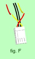
The 12 & 5 volt leads on Amstrad made drives are wired in reverse to the norm. Cutting the two outside leads and joining the left (red on my Spectrum) to the right (orange) and then the right to the left will create a cross over for the correct the power levels. ( fig. F)
Preferably use old IDC plugs without ribbon cable attached to put together the fitting as above. To make a mould (fig C), on a base board use balsa wood strips or Plasticine to hold the fitting level and to create a box with the front faces of the lDC plugs. The internal sides of the box need to be heavily smeared with vaseline. Only the connecting pins and ground wire should be inside the box. Fill the box with plastic padding (available from auto part stores). When dry the box can be dismantled and the adapter freed.


Provided with a 26 way ribbon cable with an lDC plug at each end there should be no reason why the fitting should not work in reverse so a 26 pin 3" drive from a +3 can be used as drive 0 or A on the Einstein. The Einstein's floppy disc controller uses a different system for drive ready and dose not use lines 33 & 34. Therefore these cables on the 34 wire cable or the 25 & 26 lines on the 26 way ribbon cable need not be altered. The standard power supply Y adapter for a 3 /12" should not be used for the 3" Amstrad manufactured drive without alteration. Again the 12 & 5 volt supply is the reverse for Amstrad 3" drives. Cut the two outside wires then join the left (red wire) to the right (yellow wire) and then the right to left.
Notes: 1. I have used the adapter successfully for a 3 1/2" drive on the Spectrum+3. 2. Spectrum +3 and Amstrad CPC 6128 3" Drives are interchangeable so the adapter should work for a CPC 6128. 3. Using a the adapter for a 3" drive from a Spectrum+3 on an Einstein has not been tested.
