MJR8-Mk2. An Experimental Version.
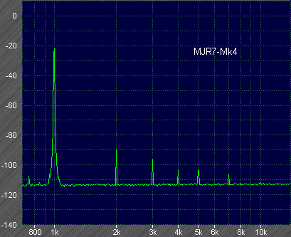
First, for reference, here is the unmodified MJR7-Mk4 1kHz distortion at 4V rms output into 7R5. As previously the -10dB level is calibrated by a 100mV signal, and the fundamental at 1kHz is nulled by over 40dB. Consequently for levels relative to 4V we need to add 22dB to the dB scale, so for example the 2nd harmonic at -90dB on the scale is at -112dB relative to the 4V output.

The only addition to the original MJR7-Mk4 circuit is a single 2SC2911 transistor, which is just a unity gain buffer stage, plus a 1k8 resistor and 100u capacitor and a 220R preset. The idea was described in the earlier MJR8 page, where a larger output inductor was suggested with a small series resistance. Keeping the smaller inductor means the buffer stage must supply more current, so for best results at high output a higher power transistor with a heatsink and higher operating current may be needed. The present circuit is just an experiment to demonstrate that the feedforward idea really does work, so it is not intended as a final design. The earlier idea to use a cfp stage was abandoned in favour of the buffer stage because of stability problems. The buffer has virtually no effect on the feedback loop, so there are no worries about stability.

And here is the untidy modification on the MJR7-Mk4 circuit board used to create this new version:

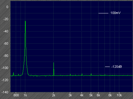
Adjusting the 220R for minimum distortion its value was then around 100R. Accurate adjustment was difficult, just bringing a finger close to the control changed the distortion level. A multi-turn preset and long insulating adjuster would be a good idea. Also it was necessary to turn off the averaging function during adjustment to see changes in harmonic levels, so they were mostly hidden under the noise. Anyway, here is an example of what is possible:

The 2nd harmonic remains at around -114dB but all the higher harmonics are reduced to better than -130dB.
There are at least two reasons why the 2nd harmonic remains stuck at about the same level as without the feedforward. One is that the inductor needs a small additional series resistance to give accurate nulling at lower frequencies, or alternatively the open-loop gain needs to continue to rise at low frequencies instead of levelling off at a few kHz.
The other reason is that the distortion of the input and driver stages has been assumed to be insignificant, and this is not entirely true. The cascode stage is no problem, and changing this to an 'enhanced cascode' made no observable difference. The problem is the emitter follower stage, or more precisely the 100R resistor from base to emitter of the emitter follower. As demonstrated in my Common Mode Distortion article the voltage Vbe across this resistor will be a function of the collector to base voltage Vcb, and will also have something like 1% 2nd harmonic distortion. The voltage changes across this resistor are also responsible for keeping the impedance at the emitter follower input down to about 200k. The cascode output impedance is much higher than this. If Vbe was constant the 100R would have a constant voltage and therefore a constant current, and in effect would behave as a high impedance.Replacing the 100R resistor by a higher impedance e.g. a jfet will help, but then a higher voltage is needed, jfets don't work well at the 0.6V Vbe, so directly replacing the resistor is not enough. Taking the jfet to the other end of the 220R bias preset gives typically 1.9V operating voltage, which may be enough, but needing to select jfets for the correct current is a disadvantage. An alternative is the LM234Z-6 adjustable current source, which has a high impedance down to 1V operating voltage, and maximum current 10mA set by a single resistor. It is also reasonably cheap, £1-18 (UK) from Farnell.
At higher input frequencies distortion nulling becomes more difficult, and some phase trimming becomes necessary. There seems little point trying to accurately null distortion components far above 20kHz except to achieve impressive specifications. With a conventional circuit low THD at 20kHz input may be a useful indicator of high frequency linearity, but with feedforward this becomes almost entirely irrelevant because all audio frequency distortion added by the output stage can in principle be nulled irrespective of its cause. It makes no difference to the nulling if a 3kHz distortion component is the 3rd harmonic of 1kHz or an intermodulation product of 17kHz plus 20kHz.
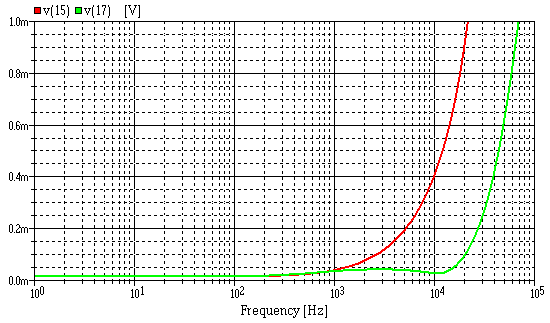
I tried a few simulations to see what frequency range the nulling was effective at, and found that increasing the emitter follower input impedance made a big difference. The next plot is probably unrealistic, it shows the distortion level based on a linear approximation in which 1% open-loop distortion is added to the output stage, and the emitter follower impedance is increased by a factor of 10. The red trace is without feedforward, and the 1.0m level is equivalent to 0.001% distortion. The distortion level at 10kHz is the level of an output distortion component at that frequency, not the distortion of a 10kHz input, so the upper limit agrees with my original specification that 'distortion components up to 20kHz are under 0.001%'. Adding the feedforward the distortion components are in green, and only rise to 0.0001% at 20kHz. This is almost certainly over optimistic, one reason being that input and driver stage distortion are ignored. What it does clearly show is how well the feedforward works to reduce output stage distortion at higher audio frequencies where feedback alone is becoming increasingly ineffective.

An improved version of the above feedforward example is currently (July 2010) 'Work In Progress' and is called the MJR-9.